Illuminating apparatus, method for fabricating the using the same and display apparatus using the same

a technology of illumination apparatus and mounting plate, which is applied in the direction of lighting and heating apparatus, point-like light sources, instruments, etc., can solve the problems of reducing the yield rate of light emitting diodes, reducing the yield rate, and reducing the number of mounting spots. , the effect of reducing the number of mounting spots

Active Publication Date: 2011-09-20
PANASONIC INTELLECTUAL PROPERTY CORP OF AMERICA +1
View PDF9 Cites 9 Cited by
  • Summary
  • Abstract
  • Description
  • Claims
  • Application Information

AI Technical Summary

Benefits of technology

[0007]It is an object of the present invention to provide a low-cost illuminating apparatus which has a reduced number of mounting spots by soldering or the like, and is capable of increasing the yield rate, a method for fabricating the illuminating apparatus, and a display apparatus using the illuminating apparatus.
[0011]With the foregoing configuration, the present invention can accomplish an illuminating apparatus which has a reduced number of mounting spots by soldering or the like to permit an increased yield rate and a reduced cost, a method for fabricating the illuminating apparatus, and a display apparatus using the illuminating apparatus.

Problems solved by technology

However, since light output of a single light emitting diode is still insufficient in applications which require high light outputs, a plurality of light emitting diodes are arrayed to make up an illuminating apparatus.
1222-1225 (2004), each package must be again mounted on a printed circuit board by soldering or the like, thus causing an increased cost for the mounting.
However, since a plurality of light emitting diodes are mounted on a series of lead frames such that they are electrically connected in series, all of the plurality of light emitting diodes are regarded as defective and discarded if even one light emitting diode is involved in defective mounting or is defective per se.

Method used


Image

  • Illuminating apparatus, method for fabricating the using the same and display apparatus using the same
  • Illuminating apparatus, method for fabricating the using the same and display apparatus using the same
  • Illuminating apparatus, method for fabricating the using the same and display apparatus using the same

Examples


first embodiment

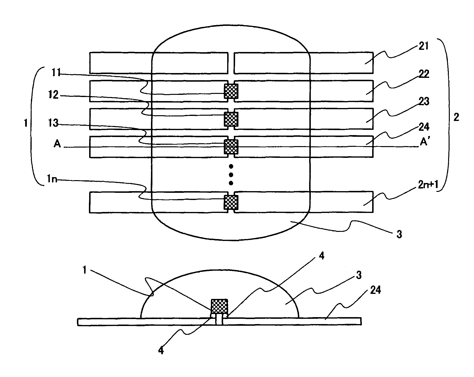
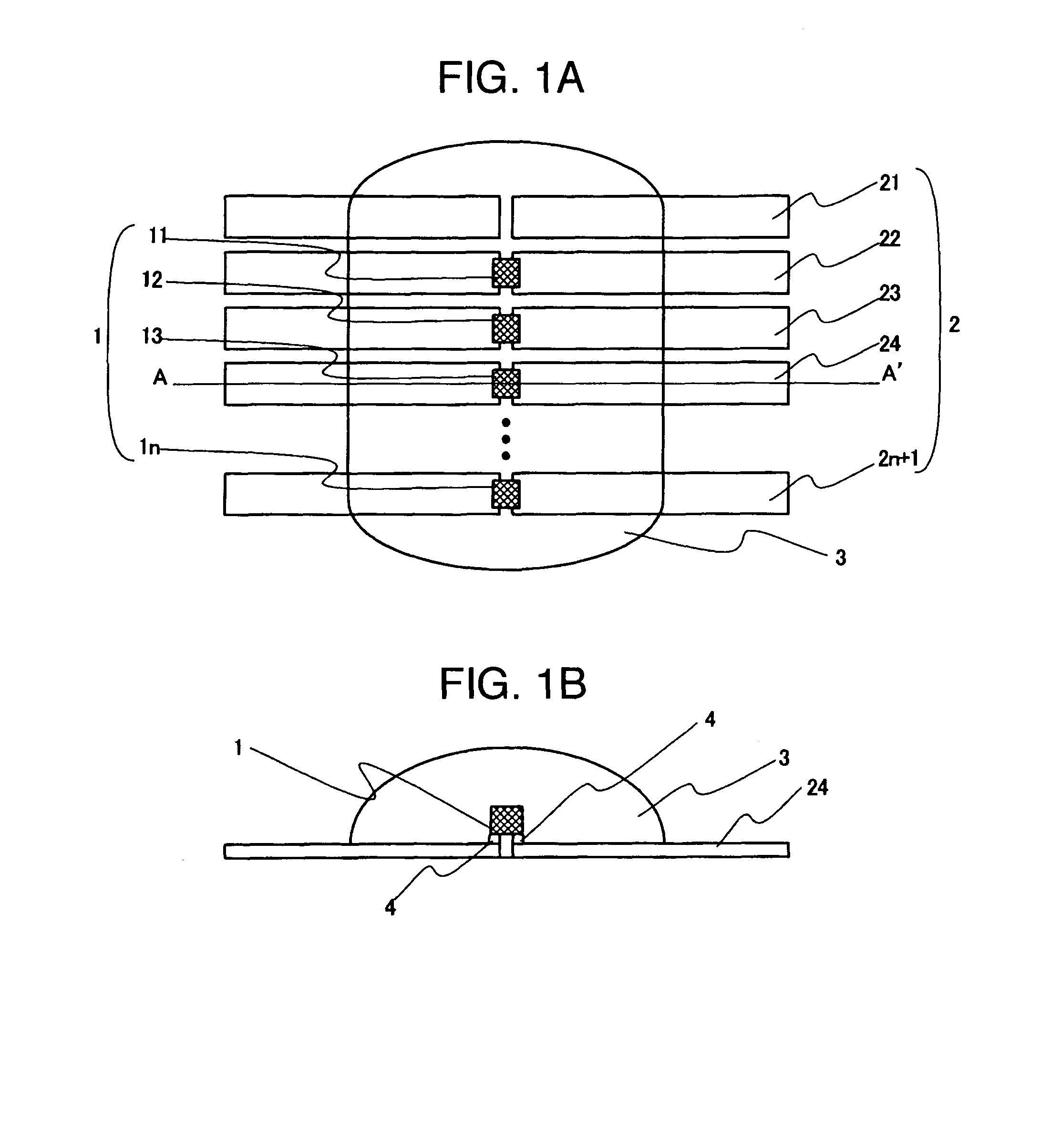
[0031]FIGS. 1A and 1B are diagrams for describing an illuminating apparatus according to a first embodiment of the present invention, where FIG. 1A shows a top plan view of the illuminating apparatus, and FIG. 1B shows a cross-sectional view taken along a line A-A′ in FIG. 1A. The illuminating apparatus of the first embodiment comprises N (N is an integer equal to or larger than one) light emitting diodes 1 (11-1n); (N+1) sets or more of lead frames 2 (21-2n+1); and a transparent sealer 3. FIG. 1 illustrates (N+1) sets of the lead frames 2. Each light emitting diode 1 is mounted on the lead frame 2 with solder 4. Then, the light emitting diodes 1 mounted on the lead frames 2 are sealed by the transparent sealer 3. In the first embodiment, the transparent sealer 3, and the light emitting diodes 1 and lead frames 2 sealed by the transparent sealer 3 are collectively referred to as a “module” which constitutes one unit. In FIG. 1, one module forms an illuminating apparatus.

[0032]In the...

second embodiment

[0044]FIG. 4 is a top plan view for describing an illuminating apparatus according to a second embodiment of the present invention. The illuminating apparatus of the second embodiment comprises N (N is an integer equal to or more than four) light emitting diodes 1, (2N−3) sets of lead frames 2, and a transparent sealer 3, where there are (N−3) sets of lead frames 2 which are not mounted with the light emitting diodes 1. FIG. 4 illustrates the illuminating apparatus which comprises five light emitting diodes (11, 12, 13, 14, 15) (N=5), and therefore seven sets of lead frames (21, 22, 23, 24, 25, 26, 27). In FIG. 4, the outermost lead frames 21, 27 are mounted with the light emitting diodes 11, 15, respectively, where they are mounted in an upper half area or a lower half area from the center lines (broken lines in FIG. 4) of the lead frames 21, 27, respectively. In addition, each of the light emitting diodes 12-14 mounted on the inner lead frames 22-26 straddles the center line of th...

third embodiment

[0052]FIG. 9 is a top plan view for describing an illuminating apparatus according to a third embodiment of the present invention, where three modules of the second embodiment described above are connected in series. Sets of lead frames, on which light emitting diodes of the modules 101, 102, 103 are mounted, are each composed of a series of lead frames which are connected in series.

[0053]FIG. 10 is a top plan view for describing a method of repairing the illuminating apparatus according to the third embodiment of the present invention. The illuminating apparatus of the third embodiment can be fabricated by similar steps to those in the first and second embodiments, and the illuminating apparatus can be formed as illustrated in FIG. 9 if all light emitting diodes are determined as conforming in the testing step. On the other hand, if any light emitting diode is determined as defective, a new light emitting diode can be mounted to make the illuminating apparatus conforming, as descri...


PUM


Abstract

An illuminating apparatus has a reduced number of mounting spots by soldering or the like to permit an increased yield rate and a reduced cost. The illuminating apparatus has light emitting diodes, lead frames, and a transparent sealer. N light emitting diodes, N sets of lead frames mounted with the N light emitting diodes, and one set or more of lead frames each not mounted with a light emitting diode are sealed by the transparent sealer for integration into a modular illuminating apparatus. Also provided are a method for fabricating the illuminating apparatus, and a display apparatus using the illuminating apparatus.

Description

CROSS-REFERENCE TO RELATED APPLICATION[0001]The present application is related to U.S. Patent Application entitled “Lighting Source Unit, Illuminating Apparatus Using the Same and Display Apparatus Using the Same” in the name of Ikuo Hiyama, Hiroki Kaneko, Toshiaki Tanaka, Tsunenori Yamamoto, Akitoyo Konno, Katsumi Kondo and Haruo Akahoshi based on Japanese Patent Application No. 2004-320383 filed on Nov. 4, 2004, and U.S. patent application entitled “Illuminating Apparatus and Display Apparatus Using the Same” in the name of Toshiaki Tanaka, Hiroki Kaneko and Ikuo Hiyama, based on Japanese Patent Application No. 2004-320136 filed on Nov. 4, 2004.BACKGROUND OF THE INVENTION[0002]The present invention relates to an illuminating apparatus using light emitting diode chips, a method for fabricating the illuminating apparatus, and a display apparatus which uses the illuminating apparatus as a back light for a non-light emitting display panel.[0003]An improved light emitting efficiency of...

Claims


Application Information

Patent Timeline
Patent Type & Authority Patents(United States)
IPC IPC(8): H01L33/00H01L33/56F21V19/00F21Y101/02H01L33/62
CPCG02F1/133603G02F2001/133612H01L25/0753H01L2224/16245H01L2224/32245H01L2224/73265H01L2224/48091H01L2924/00014G02F1/133612H01L2224/0554H01L2224/05568H01L2224/05573H01L2224/05599H01L2224/0555H01L2224/0556
Inventor KANEKO, HIROKIHIYAMA, IKUOTANAKA, TOSHIAKIADACHI, MASAYAYAMAMOTO, TSUNENORIAKAHOSHI, HARUO
Owner PANASONIC INTELLECTUAL PROPERTY CORP OF AMERICA
Why Eureka
Try Eureka