Lossless clamp of steel wire rope

A steel wire rope and clamp technology, applied in the field of wire rope tensile test clamps, can solve the problems of easy loss, complicated operation, extrusion of steel wire rope cores, etc., and achieve the effect of reducing the number of parts, reducing the number of installations, and improving work efficiency

Inactive Publication Date: 2012-11-07
SHANDONG ELECTRIC POWER TRANSMISSION & SUBSTATION ENG CO
View PDF6 Cites 9 Cited by
  • Summary
  • Abstract
  • Description
  • Claims
  • Application Information

AI Technical Summary

Problems solved by technology

The main problems are: 1. The number of saddle bolts used is large, the operation is cumbersome, and they are easy to lose; 2. The degree of clamping is difficult to grasp; 3. The contact area with the wire rope is small, and the wire rope is easy to be damaged; Core extruded, causing permanent damage

Method used


Image

  • Lossless clamp of steel wire rope
  • Lossless clamp of steel wire rope
  • Lossless clamp of steel wire rope

Examples


Embodiment 1

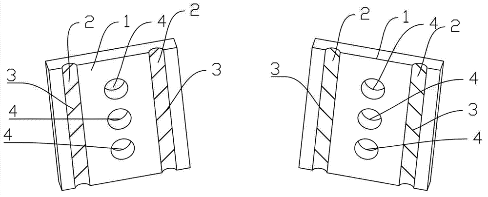
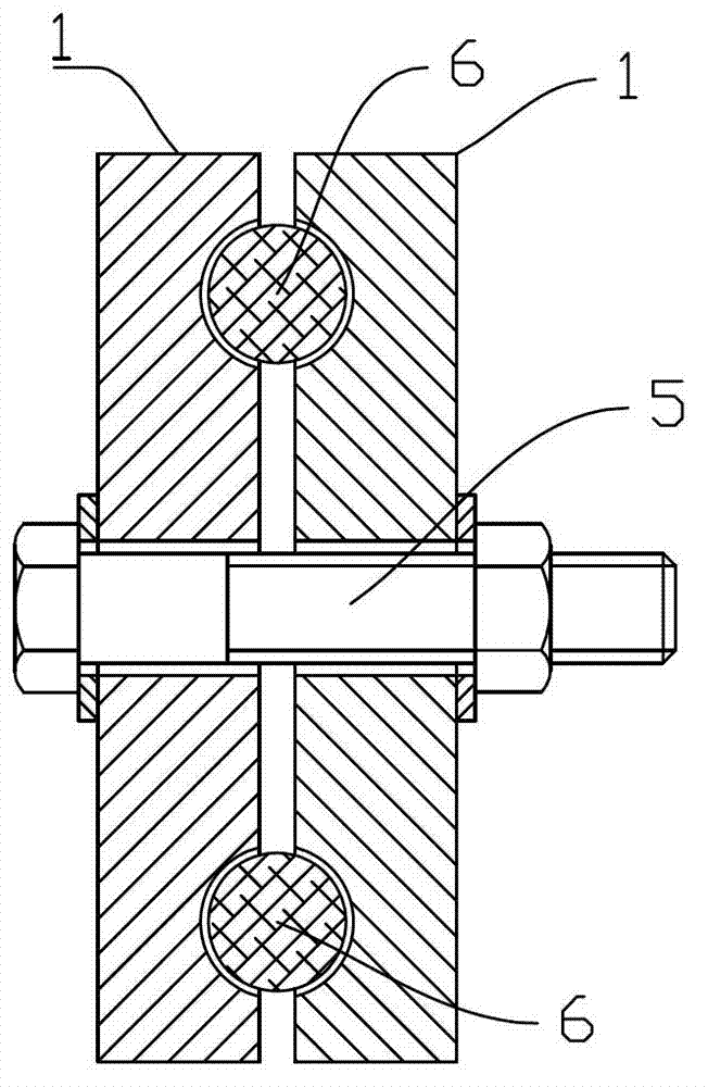
[0018] Embodiment one: if figure 1 As shown, the wire rope non-destructive fixture includes two splints 1 and connecting bolts 5 for connecting the two splints together.

[0019] The two splints 1 are respectively provided with a clamping working surface; the clamping working surfaces of the two splints are respectively provided with two arc-shaped concave linear clamping grooves 2 adapted to the outer surface of the steel wire rope, and the clamping grooves on the same clamping plate 2 are parallel to each other; the spacing between the clamping grooves on one splint is equal to the spacing between the clamping grooves on the other splint; the sum of the depths of the corresponding two clamping grooves 2 on the two splints 1 is less than diameter; the two splints 1 are correspondingly provided with a plurality of connecting holes 4 for matching with connecting bolts 5 .

[0020] In the jig, a plurality of connection holes 4 on each splint 1 are arranged in a row, and are loc...

Embodiment 2

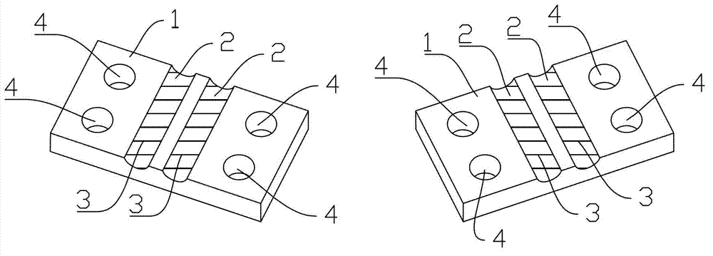
[0026] Embodiment two: if image 3 As shown, the difference from the first embodiment is that the connection holes 4 on each splint 1 in this embodiment are in two rows, and the two clamping grooves 2 are located between the two rows of connection holes 4 .

[0027] In addition, in order to ensure that the test obtains correct comparison data, the size of the splint 1 in this embodiment is 110 mm in length, 120 mm in width, and 15 mm in thickness. The axial direction along the clamping groove is the length direction.

[0028] All the other technologies are the same as in Embodiment 1.

Embodiment 3

[0029] Embodiment three: as Figure 4 As shown, the difference from Embodiment 1 is that in this embodiment, there are three connecting holes 4 on each splint 1, which are respectively located on both sides of the two clamping grooves 2 and between the two clamping grooves 2. .

[0030] During manufacture, the size of each splint 1 of the jig is 110 mm in length, 60 mm in width, and 15 mm in thickness; the axial direction along the clamping groove 2 is the length direction.

[0031] All the other technologies are the same as in Embodiment 1.


PUM


Abstract

The invention relates to a lossless clamp of a steel wire rope. The lossless clamp is characterized by comprising two clamping plates and a connecting bolt used for connecting the two clamping plates, wherein the two clamping plates are both provided with a clamping working surface; the clamping working surfaces of the two clamping plates are respectively provided with two linear clamping slots which adapt to the outer surfaces of the steel wire rope and are depressed in an arc surface shape, and the clamping slots on the same clamping plate are mutually parallel; the distance between the two clamping slots on one clamping plate is equal to the distance between the clamping slots on the other clamping plate; the summation of the depths of the corresponding clamping slots on the two clamping plates is smaller than the diameter of the steel wire rope; and the two clamping plates are correspondingly provided with a plurality of connecting holes used for matching with the connecting bolt. Due to the reduction of mounting amount of the clamp, the operation is facilitated and the efficiency is improved; in addition, as the contact area between the clamp and the steel wire rope is increased, the damages to the steel wire rope are avoided.

Description

technical field [0001] The invention relates to a jig for a steel wire rope tension test. Background technique [0002] Power supply reliability is very important for power supply system. In windy weather, if the cable of the pole is loose, it is easy to cause the pole to fall. In some strong wind areas, the distribution network lines of the power supply system are seriously affected by the strong wind all the year round, and the cable is easy to loosen, which cannot guarantee the safe operation of the cable tower. Severe rod down accidents will occur, so it is necessary to perform a tensile test on the steel wire rope used as the guy wire. [0003] When steel wire rope is carried out tension test at present, the end of steel wire rope is folded back, then adopts saddle bolt to clamp steel wire rope main body section and folded back part, makes steel wire rope chuck. The main problems are: 1. The number of saddle bolts used is large, the operation is cumbersome, and they a...

Claims


Application Information

Patent Timeline
Patent Type & Authority Applications(China)
IPC IPC(8): G01N3/04
Inventor 李涛刘仙仰高峰丁宝民孟广伟李爱军董世龙黄振鹏
Owner SHANDONG ELECTRIC POWER TRANSMISSION & SUBSTATION ENG CO
Why Eureka
Try Eureka