Abrasion-proof rotation structure

A technology of rotating structure and rotating shaft, used in rigid shaft couplings, mechanical equipment, couplings, etc., can solve the problems of easy wear, eccentricity of the rotating shaft, easy wear, etc., to prevent "eccentricity, eliminate clearance, Avoid the effect of axial slump

Inactive Publication Date: 2011-11-02
GUANGZHOU SEAGULL KITCHEN & BATH PROD
View PDF4 Cites 9 Cited by
  • Summary
  • Abstract
  • Description
  • Claims
  • Application Information

AI Technical Summary

Problems solved by technology

[0006] In order to solve the rotating structure fixed by the expansion unit in the prior art, as the use time increases, the expansion unit is prone to wear during the long-term friction with the rotating shaft, so that the expansion unit There is a gap between

Method used


Image

  • Abrasion-proof rotation structure
  • Abrasion-proof rotation structure
  • Abrasion-proof rotation structure

Examples


Embodiment 1

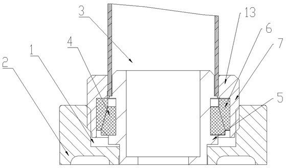
[0044] The wear-resistant rotating structure described in this embodiment is as figure 1 As shown, including: a frame 2 provided with a threaded hole 1;

[0045] A rotating shaft 3, the rotating shaft 3 is arranged in the base 2;

[0046] The rotating structure is also provided with:

[0047] an elastic inner gasket 4, the elastic inner gasket 4 is nested on the rotating shaft 3;

[0048] The limit device 5 is arranged around the rotating shaft 3 and conflicts with the bottom end of the elastic inner gasket 4;

[0049] The rotating structure also includes a pressing cover 7, the pressing cover 7 is provided with threads suitable for screwing into the threaded hole 1, and the bottom end of the pressing cover 7 and the bottom end of the threaded hole 1 have a A gap suitable for screwing in the compression cover 7;

[0050] An elastic outer gasket 6 is arranged between the pressing cover 7 and the elastic inner gasket 4, and the elastic outer gasket 6 is press-fitted with the...

Embodiment 2

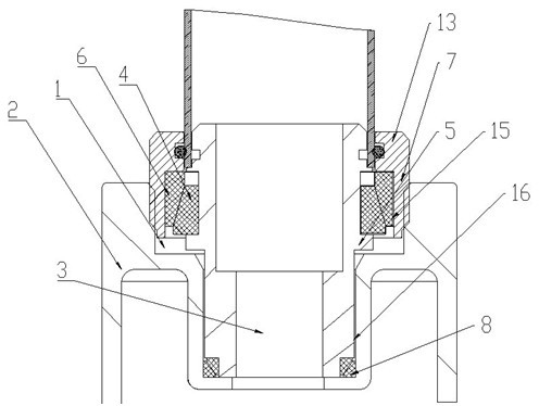
[0056] The wear-resistant rotating structure described in this embodiment is as figure 2 As shown, including: a frame 2 provided with a threaded hole 1;

[0057] A rotating shaft 3, the rotating shaft 3 is arranged in the base 2;

[0058] The rotating structure is also provided with: an elastic inner gasket 4, the elastic inner gasket 4 is nested on the rotating shaft 3;

[0059] The limit device 5 is arranged around the rotating shaft 3 and conflicts with the bottom end of the elastic inner gasket 4;

[0060] The rotating structure also includes a pressing cover 7, the pressing cover 7 is provided with threads suitable for screwing into the threaded hole 1, and the bottom end of the pressing cover 7 and the bottom end of the threaded hole 1 have a A gap suitable for screwing in the compression cover 7;

[0061] An elastic outer gasket 6 is arranged between the pressing cover 7 and the elastic inner gasket 4 , and the inner side of the pressing cover has a groove 15 for ac...

Embodiment 3

[0068] The wear-resistant rotating structure in this embodiment is as Figure 4 As shown, the difference from Embodiment 2 is that in this embodiment, the angle between the contact surface of the elastic inner gasket and the elastic outer gasket and the horizontal plane is 65°.

[0069] In this embodiment, a protective cover 14 is provided around the clamping end 13, and the protective cover 14 is threadedly connected to the clamping end 13, and the lower surface of the protective cover 14 is set in conflict with the base 2; In the rotating structure described in the embodiment, two sealing grooves 11 are formed on the rotating shaft 3 in the shaft mounting hole 16 , and O-rings 12 are arranged in the sealing grooves 11 .

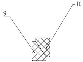
[0070] In addition, in this embodiment, the elastic inner gasket and the elastic outer gasket are non-closed sleeves, and the gap between the gaps of the non-closed sleeves is 0.5mm. As an optional implementation, the The gap at the notch can also be optio...


PUM


Abstract

The invention discloses an abrasion-proof rotation structure. The abrasion-proof rotation structure is provided with a tightening cap, wherein the tightening cap is provided with a thread suitable to be screwed into a screwed hole; an outer elastic gasket is arranged between the tightening cap and an inner elastic gasket; a contact surface between the outer elastic gasket and the inner elastic gasket is in force fit; the contact surface is gradually expanded along the direction of the tightening cap which is screwed into the screwed hole. When the abrasion-proof rotation structure is practically used and when a clearance between the inner elastic gasket and the outer elastic gasket or between the inner elastic gasket and a rotating shaft exists due to abrasion, the tightening cap is screwed up clockwise or anticlockwise along the direction of the thread on the outer wall of the tightening cap; the tightening cap is extruded to the direction of the front section of the rotating shaft along the thread; meanwhile, the outer elastic gasket downwards moves to extrude the inner elastic gasket so as to solve the problem that a fixing device in the prior art can not be normally used after abrasion.

Description

technical field [0001] The invention relates to a rotating mechanism, in particular to a wear-resistant rotating structure. Background technique [0002] Rotating structures are widely used in faucets and other equipment. The early rotating structure usually uses the clearance fit between the rigid rotating shaft and the hole to realize the rotation. Due to its high strength, this structure is usually used in occasions with high requirements on the life of the parts. However, the defect of this early rotating structure is that: because there is a gap between the shaft and the hole, the rotating shaft is easily deviated from the axial direction of the hole, that is, the phenomenon of "eccentricity" occurs. [0003] In order to solve the problem that the above-mentioned rotating shaft is easy to "eccentric", Chinese patent document CN200946620Y discloses a rotating structure, which provides a device for fixing and adjusting the rotating shaft. The rotating shaft in this paten...

Claims


Application Information

Patent Timeline
IPC IPC(8): F16D1/096
Inventor 不公告发明人
Owner GUANGZHOU SEAGULL KITCHEN & BATH PROD
Why Eureka
Try Eureka