self-calibrating gear

A self-calibrating, gear technology, applied in the direction of belts/chains/gears, components with teeth, portable lifting devices, etc., can solve the problem of not being able to adjust the meshing of gear pairs by itself, so as to prevent axial movement and ensure sensitivity Effect

Inactive Publication Date: 2011-12-07
NANJING HIGH SPEED & ACCURATE GEAR GRP
View PDF4 Cites 5 Cited by
  • Summary
  • Abstract
  • Description
  • Claims
  • Application Information

AI Technical Summary

Problems solved by technology

[0003] The purpose of the present invention is to provide a new self-calibrating gear for the actual problem that the current gear and the shaft cannot adjust the meshing of the gear pair by itself after the rigid connection is adopted.

Method used


Image

  • self-calibrating gear
  • self-calibrating gear
  • self-calibrating gear

Examples


Embodiment Construction

[0015] The accompanying drawings disclose the specific structures of the embodiments of the present invention without limitation, and the present invention will be further described below in conjunction with the accompanying drawings.

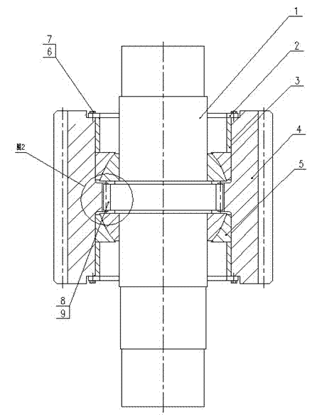
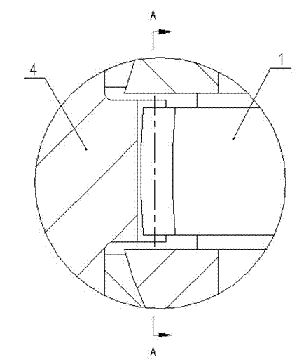
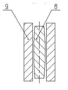
[0016] Depend on figure 1 It can be seen that the axis center of gear 4 is shaft 1, a section of protruding external spline is provided in shaft 1, and a section of protruding internal spline is provided in the assembly hole of gear 4. The length of the internal spline is the same as that of the external spline. Corresponding to the key; corresponding to the front and rear ends of the outer spline section and the inner spline, the joint bearing 5 is respectively provided, and the adjustment ring 3 and the pressure plate 2 are arranged in turn between the joint bearing 5 and the end face of the gear 4, and the pressure plate 2 is fixed on the gear 4 by bolts. end face. Shaft 1 and gear 4 are positioned by joint bearing 5 .

[0017] In this emb...


PUM


Abstract

The invention relates to a self-calibrating gear, including a gear, wherein: the shaft center of the gear is a shaft, a section of protruding external spline is arranged in the shaft, and a section of protruding internal spline is arranged in the gear assembly hole, the length of which is Corresponding to the external spline; the external spline is a convex arc along the axial direction, and its highest point is located at half of the external spline, and the axial arc of the internal spline is in line with the The convex arcs of the external splines match and mesh with each other; the front and rear ends of the external splines and internal splines are respectively provided with joint bearings, and an adjustment ring and a pressure plate are arranged between the joint bearing and the end face of the gear in turn, and the pressure plate passes through The bolt is fixed on the end face of the gear.

Description

technical field [0001] The invention relates to a gear with specific functions, in particular to a self-calibrating gear which can automatically compensate installation errors. Background technique [0002] At present, the traditional connection between the gear and the shaft is usually a key connection or an interference connection. These connection methods are simple in structure and mature in application, but these connection methods are all rigid connections. Compared with the requirements for parts manufacturing and assembly adjustment, when these When the connection method is used in some occasions where the manufacturing precision of some parts is low or cannot be adjusted accurately, it will seriously affect the strength and running stability of the gear. How to make the gear pair run smoothly without reducing the load-carrying capacity of the gear even when the manufacturing precision of the parts is low or cannot be adjusted accurately has become a problem that peo...

Claims


Application Information

Patent Timeline
Patent Type & Authority Applications(China)
IPC IPC(8): F16D3/18F16H55/17
Inventor 杨虎杨静袁帅刘增民
Owner NANJING HIGH SPEED & ACCURATE GEAR GRP
Why Eureka
Try Eureka