Pohotonic crystal fiber and pohotonic crystal fiber sensor

A photonic crystal fiber and sensor technology, applied in cladding fibers, microstructure fibers, optical waveguides and light guides, etc., can solve the difficulty of filling metal nanocoatings and microfluids to be measured, unfavorable signal transmission, and loss of photonic crystal fibers in the measurement band Increase and other problems to achieve the effect of ensuring sensing accuracy, simple and fast operation process, and real-time sensing measurement

Inactive Publication Date: 2015-01-21
NORTH CHINA UNIV OF WATER RESOURCES & ELECTRIC POWER
View PDF2 Cites 22 Cited by
  • Summary
  • Abstract
  • Description
  • Claims
  • Application Information

AI Technical Summary

Problems solved by technology

[0006] The purpose of the present invention is to provide a kind of photonic crystal fiber and photonic crystal fiber sensor, in order to solve the problem that the diameter of the air hole as the microfluid channel is too small, it is difficult to fill the metal nano-coating film and the microfluid to be measured; When the value is large, the loss of the photonic crystal fiber in the measurement band will increase significantly, which is not conducive to the problem of signal transmission

Method used


Image

  • Pohotonic crystal fiber and pohotonic crystal fiber sensor
  • Pohotonic crystal fiber and pohotonic crystal fiber sensor
  • Pohotonic crystal fiber and pohotonic crystal fiber sensor

Examples


Embodiment Construction

[0024] The present invention will be further described in detail below in conjunction with the drawings.

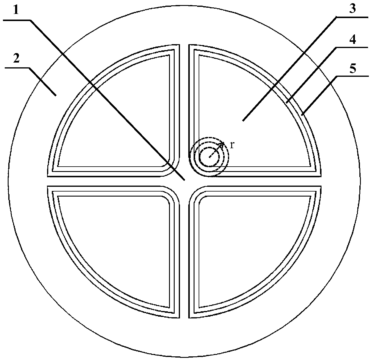
[0025] A photonic crystal fiber includes: a cladding, a core, and at least one air hole in the cladding; the cross section of the air hole is fan-shaped, the arc surface of the air hole is set away from the core, and the inner wall of the air hole is plated first There is a calcium fluoride film, followed by a gold nano film.

[0026] A photonic crystal fiber sensor includes a photonic crystal fiber. The photonic crystal fiber includes a cladding, a core, and at least one air hole in the cladding; the cross section of the air hole is fan-shaped, and the arc surface of the air hole is away from the fiber. The core is arranged, and the inner wall of the air hole is first plated with a calcium fluoride film and then with a gold nano film.

[0027] Based on the above technical solution and in conjunction with the drawings, the following specific implementation is given.

[0028] Suc...


PUM

PropertyMeasurementUnit
radiusaaaaaaaaaa
thicknessaaaaaaaaaa
thicknessaaaaaaaaaa

Abstract

The invention relates to a pohotonic crystal fiber and a pohotonic crystal fiber sensor. The pohotonic crystal fiber comprises a cladding, a fiber core and at least one air hole; the cross section of the air hole is in a sector shape, the arc-shaped face of the air hole is far away from the fiber core, and the inner wall of the air hole is firstly plated with calcium fluoride thin film and then plated with metal nano thin film. The pohotonic crystal fiber sensor is further provided. The pohotonic crystal fiber and the pohotonic crystal fiber sensor have the advantages that the outer diameter of the pohotonic crystal fiber is 125 micrometers, and therefore operation such as coupling and fusing between fibers in an optical network can be quite conveniently achieved. Filling of the metal nano thin film and to-be-detected microfluid is easily achieved through the large diameter of the air hole, selective film plating is not needed in the operation, and the sensing accuracy is guaranteed. The operation process is simple and rapid, and real-time sensing measurement on environmental media can be achieved. A double-layer film plating operation mode is provided, transmission losses of the pohotonic crystal fiber can be effectively reduced, and the sensing stability and the sensing flexibility are improved.

Description

Technical field [0001] The invention relates to a photonic crystal fiber and a photonic crystal fiber sensor, belonging to the technical field of photonic crystal fiber sensing. Background technique [0002] Since the 1980s, low-loss optical fiber transmission has become a reality, and the use of optical fiber technology for sensing has gradually become a frontier topic in the development of sensor technology. Compared with traditional sensors, optical fiber sensors have the characteristics of small size, light weight, anti-electromagnetic interference, high sensitivity, and easy formation of optical fiber sensing networks. They are used in national defense, communications, industrial production and processing, precision detection of biomedicine, optical network construction, etc. The field shows its strong advantages. [0003] Photonic crystal fiber is also called micro-structure fiber. It usually contains air holes in different arrangements. Therefore, the refractive index distr...

Claims


Application Information

Patent Timeline
Patent Type & Authority Applications(China)
IPC IPC(8): G02B6/02G01N21/552
CPCG01N21/552G02B6/02295G02B6/02314
Inventor 邴丕彬李忠洋袁胜周玉段爱霞朱安福杨阳
Owner NORTH CHINA UNIV OF WATER RESOURCES & ELECTRIC POWER
Why Eureka
Try Eureka