
Projection device

A projection device and projection technology, applied to projection devices, projectors with built-in screens/external screens, optics, etc., can solve the problems of heavy weight of projection devices, and achieve the effect of solving overweight and reducing the number of lenses

Active Publication Date: 2013-03-06
QISDA OPTRONICS (SUZHOU) CO LTD +1
View PDF0 Cites 0 Cited by
  • Summary
  • Abstract
  • Description
  • Claims
  • Application Information

AI Technical Summary

Problems solved by technology

[0005] The main purpose of the present invention is to provide a projection device to improve the problem of excessive weight of the projection device caused by shortening the focal length

Method used


Image

  • Projection device
  • Projection device
  • Projection device

Examples


Embodiment Construction

[0018] In order to have a further understanding of the purpose, structure, features, and functions of the present invention, the following detailed descriptions are provided in conjunction with the embodiments.

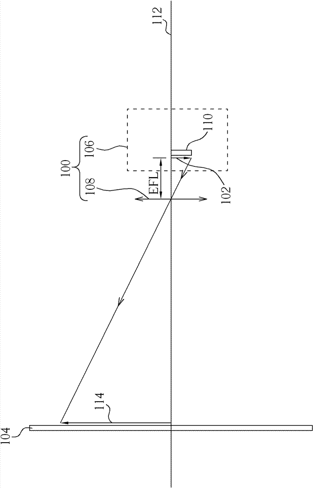
[0019] Please refer to figure 2 , figure 2 It is a schematic diagram of the projection device of the present invention. Such as figure 2 As shown, the projection device 100 is used to project an image 102 onto a projection screen 104 , and the projection device 100 includes an image generating device 106 and a projection lens 108 . Wherein, the image generating device 106 is used for generating the projection light with the image 102 . The image generating device 106 has a light valve 110 and emits projection light from the light valve 110 . The image generating device 106 of this embodiment can be a light engine including a light source, various optical elements, etc., and the light valve can be, for example, a liquid crystal panel (LCD panel), a digital micro...


PUM


Abstract

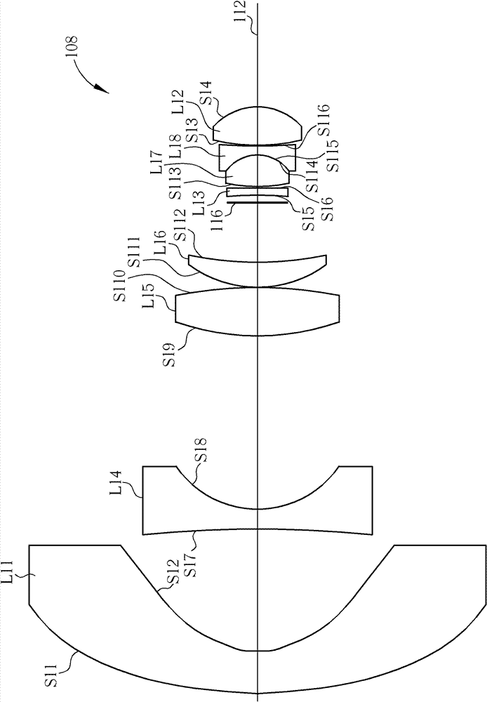
The invention provides a projection device which comprises an image generation device and a projection lens. The projection lens is arranged between a light valve of the image generation device and a projection screen, and the projection lens comprises a plurality of lenses. The lenses comprise a first lens, a second lens and a third lens which are aspherical lenses. The effective focal length ofthe projection lens is between 5mm and 8mm, and the sum of the effective focal length millimeter value of the projection lens and the lens number is between 14 and 17. According to the invention, theprojection device can achieve the effects of short focal length and large projection angle, thus the lens number of the projection device can be effectively reduced and the problem of overweight projection device can be further solved.

Description

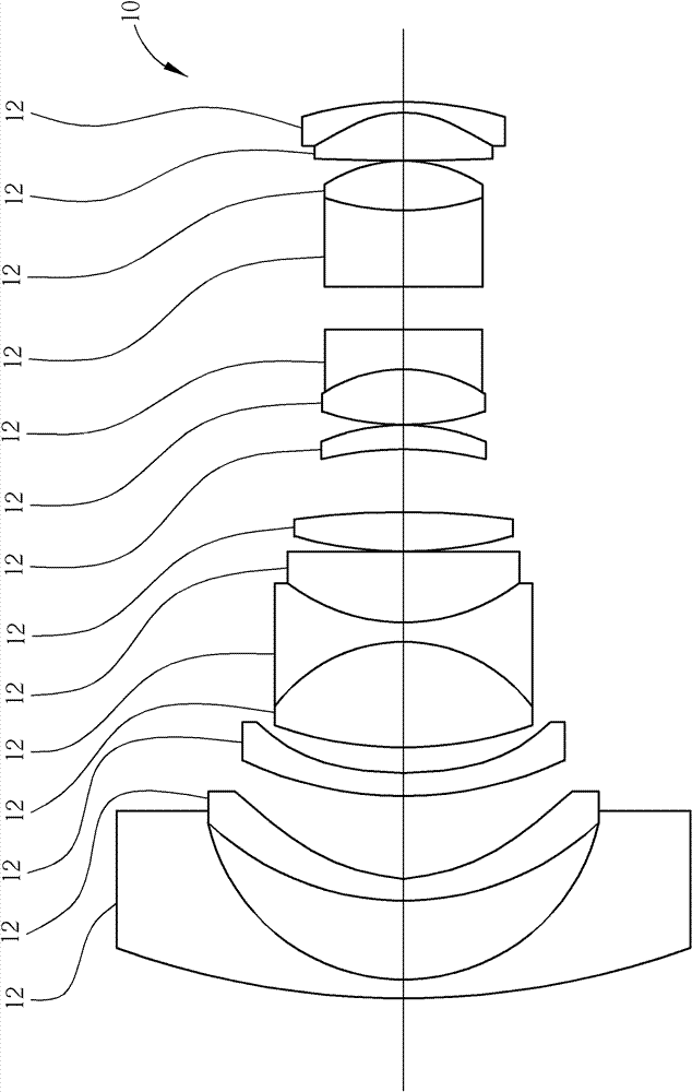
technical field [0001] The present invention relates to a projection device, in particular to a projection device with a projection lens having at least three aspherical lenses. Background technique [0002] With the rapid development of technology, projection devices have gradually played an indispensable role in family, entertainment or business purposes. A traditional projection device is composed of an image generating device and a projection lens, and the image generated by the image generating device is enlarged by the projection lens and projected onto a projection screen. [0003] Since the lenses used to make projection lenses in the past are designed with spherical surfaces, many lenses need to be used in the projection lens to solve problems such as aberration and image blur and out of focus, which limits the size and weight of the projection lens. Please refer to figure 1 , figure 1 It is a schematic diagram of a conventional projection lens. Such as figure ...

Claims


Application Information

Patent Timeline
Patent Type & Authority Patents(China)
IPC IPC(8): G03B21/14G03B21/10G02B13/00G02B13/18G02B13/06
Inventor 林明坤吴宗训
Owner QISDA OPTRONICS (SUZHOU) CO LTD
Learn More