Clock synchronization method and apparatus in transmission system

A clock synchronization and transmission system technology, applied in the field of communication, can solve the problem of low system clock synchronization accuracy, and achieve the effect of improving the clock synchronization accuracy

Active Publication Date: 2011-11-02
ZTE CORP
View PDF1 Cites 25 Cited by
  • Summary
  • Abstract
  • Description
  • Claims
  • Application Information

AI Technical Summary

Problems solved by technology

[0009] The main purpose of the present invention is to provide a clock synchronization method and device in a transmission system to at least solve the problem of low system clock synchronization accuracy in the prior art

Method used


Image

  • Clock synchronization method and apparatus in transmission system
  • Clock synchronization method and apparatus in transmission system
  • Clock synchronization method and apparatus in transmission system

Examples


Embodiment 1

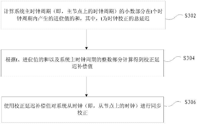
[0033] image 3 It is a preferred flowchart of a clock synchronization method in a transmission system according to an embodiment of the present invention, which includes the following steps:

[0034] S302. Calculate the sum of the carry values ​​generated within t clock cycles of the fractional part of the main clock cycle of the system (that is, the clock cycle on the master node), where t is the total delay of clock correction;

[0035] S304, calculate and obtain the correction delay compensation value according to the sum of t, the carry value and the integer part of the system main clock cycle;

[0036] S306. Use the corrected delay compensation value to perform synchronous correction on the system slave clock (that is, the clock on the slave node).

[0037] In this embodiment, the carry value of the fractional part of the system master clock period is used as a part of the compensation value, so as to realize accurate compensation for the integer part and thus accuratel...

Embodiment 2

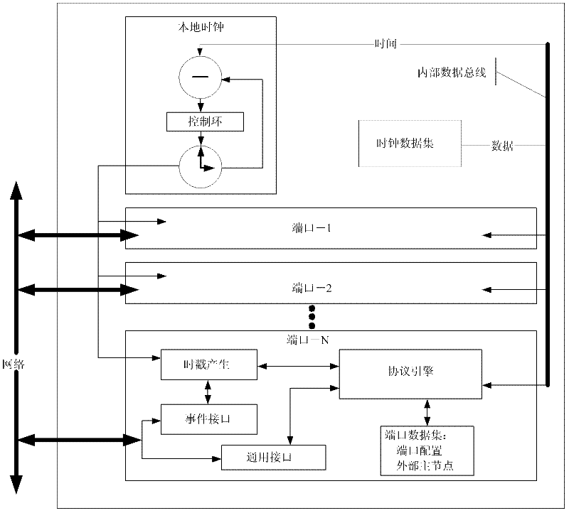
[0077] Figure 8 is a preferred structural diagram of a clock synchronization device in a transmission system according to an embodiment of the present invention, which includes: a computing unit 802, used to calculate the sum of the carry values ​​generated within t clock cycles of the fractional part of the main clock cycle of the system, where , t is the total delay of clock correction; the correction delay compensation value is calculated according to the sum of the t, the carry value and the integer part of the system master clock cycle; the synchronization unit 804 is used to use the correction delay compensation value Synchronize the system slave clock.

[0078] In this embodiment, the carry value of the fractional part of the system master clock period is used as a part of the compensation value, so as to realize accurate compensation for the integer part and thus accurately compensate the fractional part of the slave clock during the calibration process.

[0079] The...


PUM


Abstract

The invention provides a clock synchronization method and an apparatus in a transmission system. The method comprises the addition of carry values generated by the decimal portion of a system station clock period in t clock periods is calculated, wherein t is the total delay of a clock correction; a correction delay compensation value is calculated through t, the addition of the carry values and the integer portion of the system station clock period and the correction delay compensation value is used to carry out a synchronization correction towards a system subordinated clock. According to the invention, the problem in the prior art that the precision of system clock synchronization is low is solved and the clock synchronization precision of the system is increased.

Description

technical field [0001] The present invention relates to the communication field, in particular to a clock synchronization method and device in a transmission system. Background technique [0002] In a mobile communication network, strict synchronization between base stations is required to ensure that users will not experience disconnection or other faults when switching between base stations during the mobile process. Currently, only GPS and IEEE 1588 can meet this requirement. The GPS time synchronization solution needs to install a receiving system at each base station, which is quite costly and requires strict installation conditions. At the same time, because GPS is controlled by the United States, the security of the system cannot be guaranteed in extraordinary times. IEEE 1588 only needs a high-precision clock source to be input to the bearer network, and then the clock information can be transmitted to each base station to achieve synchronization across the network. ...

Claims


Application Information

Patent Timeline
Patent Type & Authority Applications(China)
IPC IPC(8): H04W56/00
Inventor 张浩明夏志国彭建辉范其蓬
Owner ZTE CORP
Why Eureka
Try Eureka