Torsion spring installing device

An installation device and torsion spring technology, applied in the field of machining, can solve the problems of injury to installation workers, high risk, time-consuming and labor-intensive, etc.

Inactive Publication Date: 2011-11-09
SIP GOLDWAY TECH
View PDF6 Cites 7 Cited by
  • Summary
  • Abstract
  • Description
  • Claims
  • Application Information

AI Technical Summary

Problems solved by technology

At present, the manual method is usually used, which is time-consuming and labor-i

Method used


Image

  • Torsion spring installing device
  • Torsion spring installing device
  • Torsion spring installing device

Examples


Embodiment Construction

[0013] Specific embodiments of the present invention will be further described in detail below.

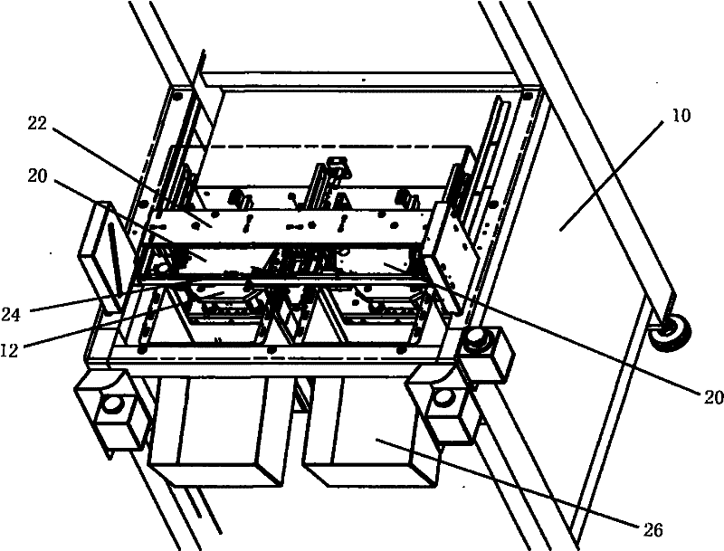
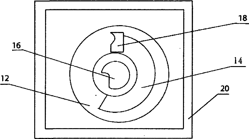
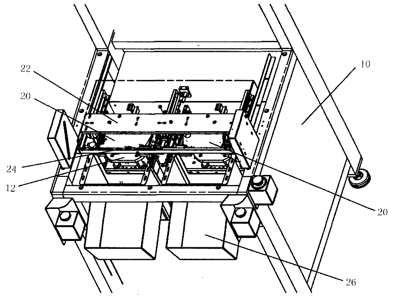
[0014] Such as figure 1 As shown, a torsion spring installation device of the present invention includes a cabinet body 10 on which two torsion spring stretching devices 12 are arranged side by side. Vertical slide rails (not shown) are arranged on the cabinet body 10, and two torsion spring tensioning devices 12 are installed on the slide rails through a bracket (not shown). A first cylinder (not shown) is vertically arranged below the torsion spring tensioning device 12, and the first cylinder can drive two torsion spring tensioning devices 12 to move up and down along the vertical slide rail. Each torsion spring tensioning device 12 includes an upwardly protruding central hook 16 and a rotatable peripheral hook 18, wherein the peripheral hook 18 is driven by a rotary cylinder (not shown) along the arc-shaped slot provided on the torsion spring tensioning device 12 14 spins. ...


PUM


Abstract

The invention discloses a torsion spring installing device. The torsion spring installing device comprises a cabinet body and is characterized in that: the cabinet body is provided with at least one torsion spring stretching device capable of moving vertically, the torsion spring stretching device comprises an upwards raised central hook and a peripheral hook capable of rotating, and a torsion spring plate bracket is arranged above the torsion spring stretching device. According to the torsion spring installing device, the hook of a torsion spring is driven through a cylinder to rotate, so that the hook moves to an installation position and is installed on the hook of a torsion spring plate; and after the installation is completed, the bracket is turned over, so that the installed finished product automatically falls to a lower collecting box. The whole process is controlled by a programmable logic controller (PLC); and the torsion spring installing device has the advantages of high degree of automation, convenience in operation, high efficiency and the like.

Description

technical field [0001] The invention belongs to the field of mechanical processing, and in particular relates to a torsion spring installation device. Background technique [0002] A torsion spring is a widely used elastic device, which is formed by bending a slender elastic material into a disk shape, and its two ends are provided with curved hooks for connecting with other parts, which forms a A hook in the center and a hook on its outer circumference. Because the torsion spring is elastic, and it is generally necessary to bring some elasticity when installing, it is difficult to install. For example, there is a torsion spring disk in auto parts, which has a rotatable part. A hook is provided on the rotatable part and the non-rotatable part of the torsion spring disk. hooks on the outside. How to install the torsion spring on the torsion spring disk has become an urgent problem to be solved. At present, the manual method is usually used, which is time-consuming, labor-...

Claims


Application Information

Patent Timeline
IPC IPC(8): B25B27/14
Inventor 沈皓然
Owner SIP GOLDWAY TECH
Why Eureka
Try Eureka