Supercharge Your Innovation With Domain-Expert AI Agents!

Printing defvice, method for controlling printing device, and computer program

A technology of printing device and control unit, applied in the direction of printing device, printing, etc.

Active Publication Date: 2011-11-09
SEIKO EPSON CORP
View PDF6 Cites 9 Cited by
  • Summary
  • Abstract
  • Description
  • Claims
  • Application Information

AI Technical Summary

Problems solved by technology

[0004] In the prior art described above, there is room for improvement in terms of both the improvement of the print quality and the suppression of the increase in the time required for the print process.
In particular, in the prior art described above, by suppressing the positional deviation along the main scanning direction of the line substantially parallel to the conveyance direction (sub-scanning direction) of the printing medium formed with the achromatic ink, the printing quality brought There is room for improvement in terms of both the improvement of the printing process and the suppression of the increase in the time required for printing processing.

Method used


Image

  • Printing defvice, method for controlling printing device, and computer program
  • Printing defvice, method for controlling printing device, and computer program
  • Printing defvice, method for controlling printing device, and computer program

Examples


no. 1 Embodiment

[0061] A-1. Configuration of printing device

[0062] A-2. Recording method

no. 2 Embodiment

[0064] C. The third embodiment

[0065] D. Fourth embodiment

[0066] E. Variation

[0067] A. The first embodiment

[0068] A-1. Configuration of printing device

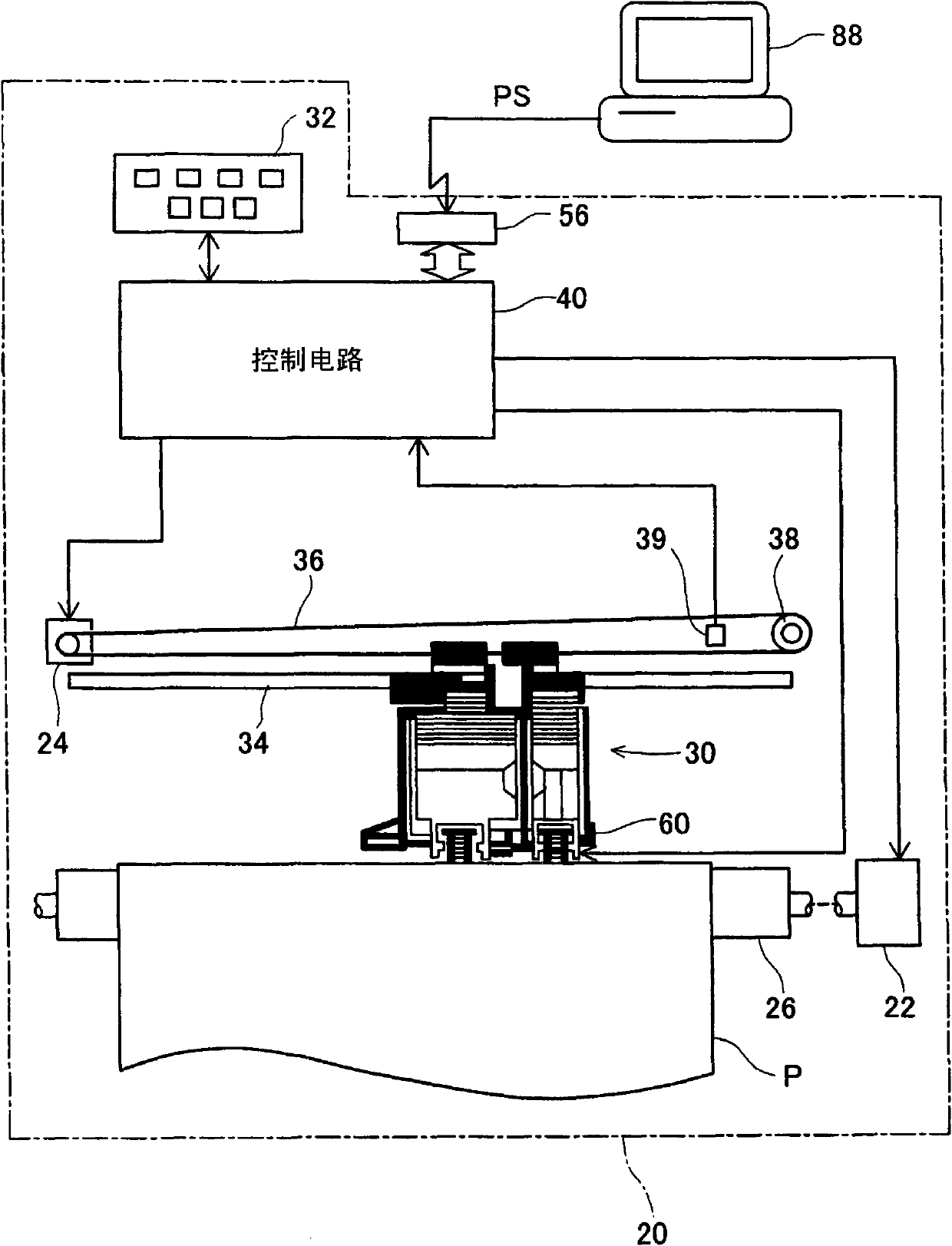
[0069] figure 1 It is a schematic configuration diagram of the printing system in the first embodiment of the present invention. The printing system of the first embodiment includes: an inkjet printer 20 ; and a computer 88 that supplies a print signal PS to the inkjet printer 20 . The inkjet printer 20 is connected to a computer 88 via a connector 56 .

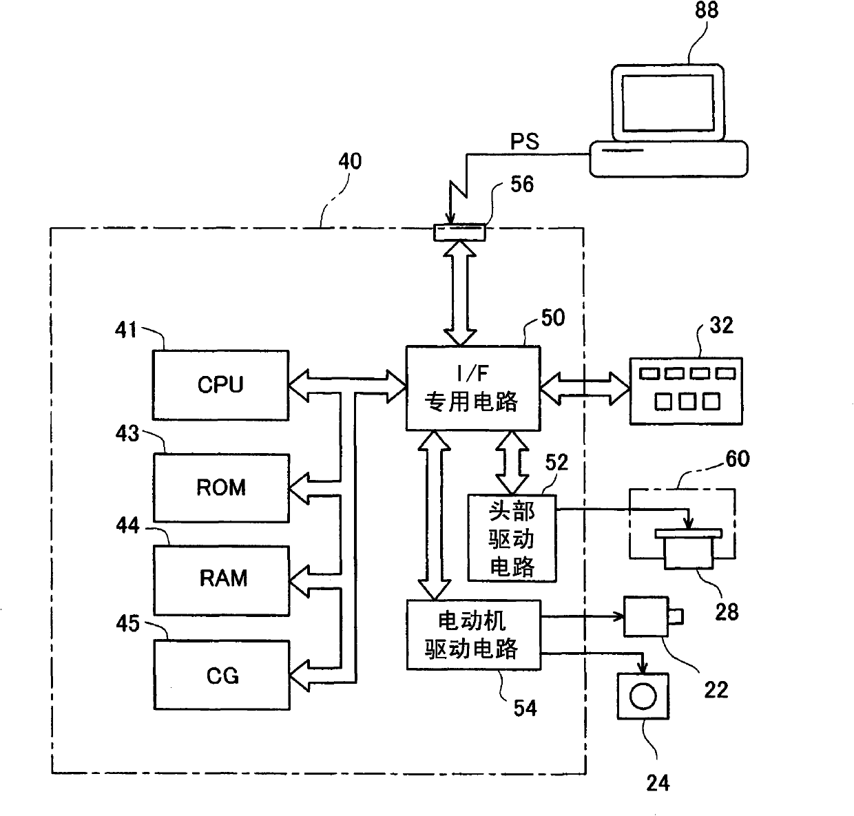
[0070] The inkjet printer 20 is provided with: a moving mechanism that performs main scanning in which the carriage 30 reciprocates in a direction parallel to the axis of the platen 26; ) that conveys the paper P as a printing medium; the print head unit 60 mounted on the carriage 30 ; and the control circuit 40 that controls each part of the inkjet printer 20 .

[0071] The transport mechanism for transporting the paper P includes a paper feed motor 22 and...


PUM


Abstract

A printing defvice, a method for controlling printing device, and a computer program. The printing device includes a nozzle row for chromatic ink comprising K nozzles, a nozzle row for achromatic ink comprising (nK) nozzles, and a control portion. In a color region, an image-forming operation is performed m times in which the movement direction of the nozzle rows switches alternately between forward and reverse directions, whereby a region of the image having a predetermined width is foamed along a first direction of an image. The image-forming operation performed m times includes the image-forming operation performed once in which both of the nozzle rows for chromatic ink and for achromatic ink are used, and the image-forming operation performed (m-1) times in which only the nozzle row for chromatic ink is used. In a monochrome region, the image-forming operation is performed once in which only the nozzle row for achromatic ink is used, whereby a region of the image having a predetermined width is formed. Therefore, the print period increase is suppressed and the print quality is enhanced.

Description

technical field [0001] The present invention relates to printing that ejects ink and forms an image on a printing medium. Background technique [0002] In recent years, printing devices that print images by ejecting ink from nozzles provided on the print head to form ink dots on a print medium while performing a main scan that reciprocates the print head have been popularized. In such a printing device, a technology is disclosed that utilizes a nozzle array for achromatic color that ejects achromatic ink (for example, black ink) and a nozzle row that ejects color ink (for example, cyan ink, magenta ink, yellow ink). The color nozzle row forms a chromatic region in a printed image, and the achromatic nozzle row only forms a black-and-white region in a printed image that does not contain a color (for example, refer to Patent Document 1). [0003] Patent Document 1: JP Unexamined Publication No. 2006-231930 [0004] In the prior art described above, there is room for improvem...

Claims


Application Information

Patent Timeline
Patent Type & Authority Applications(China)
IPC IPC(8): B41J2/01B41J29/393
CPCB41J2/2132
Inventor 佐藤彰人石本文治宫下隆秀杉山克彦竹内康弘
Owner SEIKO EPSON CORP
Features
  • R&D
  • Intellectual Property
  • Life Sciences
  • Materials
  • Tech Scout
  • Unparalleled Data Quality
  • Higher Quality Content
  • 60% Fewer Hallucinations
Learn More