Lubricant circuit

A lubricant and lubricant pump technology, applied in the direction of pressure lubricant, lubrication pump, control lubricant pressure, etc., can solve problems such as energy loss

Inactive Publication Date: 2011-11-09
GM GLOBAL TECH OPERATIONS LLC
View PDF0 Cites 10 Cited by
  • Summary
  • Abstract
  • Description
  • Claims
  • Application Information

AI Technical Summary

Problems solved by technology

Although the cold start valve provides effective protection against critically high pressures in the lubricant circuit, each time lubricant passes through the cold start valve, energy is lost unused

Method used


Image

  • Lubricant circuit
  • Lubricant circuit
  • Lubricant circuit

Examples


Embodiment Construction

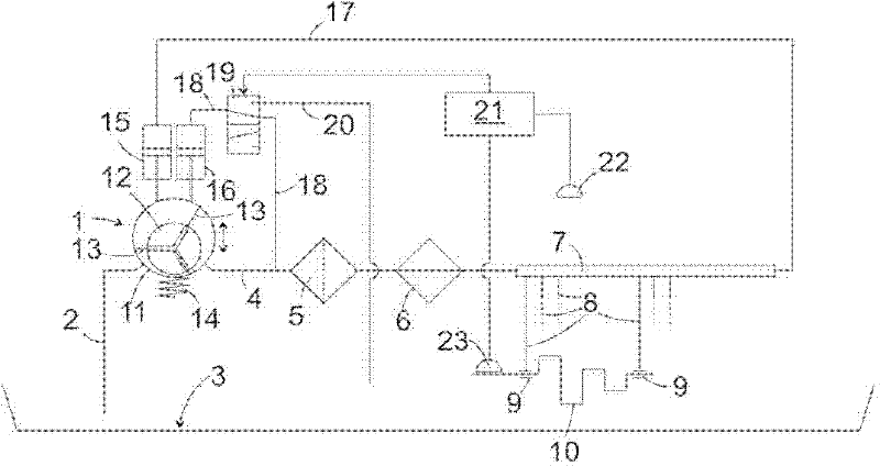
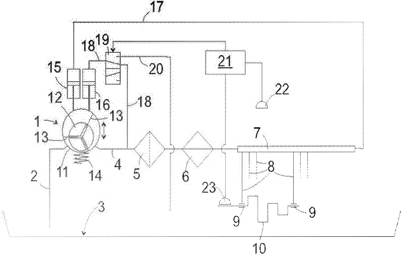
[0023] figure 1 is a schematic diagram of the lubricating oil circuit in an automobile engine. The vane pump 1 is connected with the oil pan 3 through the oil inlet pipe 2 . The distributor connected to the pressure side of the vane pump 1 includes an input line 4 and an oil passage 7, and a lubricating oil filter 5 and a lubricating oil cooler 6 are connected in series on this input line 4. From this oil Branched off from the duct 7 are branch lines 8 connected to different lubrication points 9 of the engine, for example the bearings of the crankshaft 10 . The lubricating oil flows unguided from the lubricating points 9 back into the oil sump 3 .

[0024] The vane pump 1 has, in a manner known per se, a housing 11 with a cylindrical cavity, in which a rotor 12 is arranged with a plurality of vanes 13 which are connected to the housing 11 via positioning rings. The inner surfaces of the cavity remain in contact and divide the cavity into multiple small chambers. The rotor ...


PUM


Abstract

The invention relates to a lubricant circuit for an internal combustion engine. The lubricant circuit includes a lubricant pump (1), which is connected on the suction side to a reservoir (3) and on the pressure side to a distributor (4, 7), at least one lubricating point (9), which is connected to the distributor (4, 7) and a return leading to the reservoir (3), and an electronic control unit (21), which is set up to regulate the output pressure of the lubricant pump (1) by reference to the temperature of the lubricant.

Description

technical field [0001] The invention relates to a lubricant circuit, in particular for lubricating internal combustion engines, such as gasoline or diesel engines in motor vehicles. Background technique [0002] Since the lubricant requirement of such an internal combustion engine increases with its rotational speed, the lubricant circuit generally includes a lubricant pump which is permanently coupled to the output shaft of the internal combustion engine and is driven by the internal combustion engine. Due to this coupling, the flow rate of the lubricant pump increases with the rotational speed of the internal combustion engine. Since the engine lubricant flow is not exactly linearly proportional to the rotational speed but is related to other factors, notably the temperature of the internal combustion engine, the lubricant pump must be designed to provide a sufficient quantity of lubricant under all operating conditions. If the quantity of lubricant delivered by the pump ...

Claims


Application Information

Patent Timeline
Patent Type & Authority Applications(China)
IPC IPC(8): F01M1/02F01M5/00F16N13/22
CPCF01M1/16F01M2001/0246F01M2001/0238F01M2250/60
Inventor 乔格.兹维克勒
Owner GM GLOBAL TECH OPERATIONS LLC
Why Eureka
Try Eureka