Band clamp

a technology of hose clamping and clamping rod, which is applied in the direction of hose connection, transportation and packaging, mechanical equipment, etc., can solve the problems of material failure at the aperture or window edge, and achieve the effect of facilitating the closing of the clamping rod without affecting the transmission of for

Active Publication Date: 2012-10-16
OETIKER SCHWEIZ AG
View PDF14 Cites 2 Cited by
  • Summary
  • Abstract
  • Description
  • Claims
  • Application Information

AI Technical Summary

Benefits of technology

[0009]The configuration of the force transmitting means in one contemplated embodiment is desirable because cup-shaped embossments in the band material increase the stability of the material rather than decreasing it.
[0010]The at least partially rounded shape of the embossments in one contemplated embodiment avoids stress peaks in the force transmitting area. The shape contemplated for another embodiment is advantageous also from the manufacturing standpoint.
[0011]In one contemplated embodiment of the invention, the embossments engage one another with play, which facilitates the closing of the clamp without impairing the force transmission.

Problems solved by technology

It has been found that, when the tensile forces to be transmitted are increased, material failure will occur at these aperture or window edges.

Method used


Image

  • Band clamp
  • Band clamp

Examples


Embodiment Construction

[0022]The invention will now be described in connection with one or more contemplated embodiments. The embodiment(s) described is(are) not intended to be limiting of the invention. To the contrary, the embodiment(s) is(are) intended to illustrate the scope and breadth of the invention. As should be appreciated by those skilled in the art, numerous variations and equivalents also are contemplated to be encompassed by the scope of the invention.

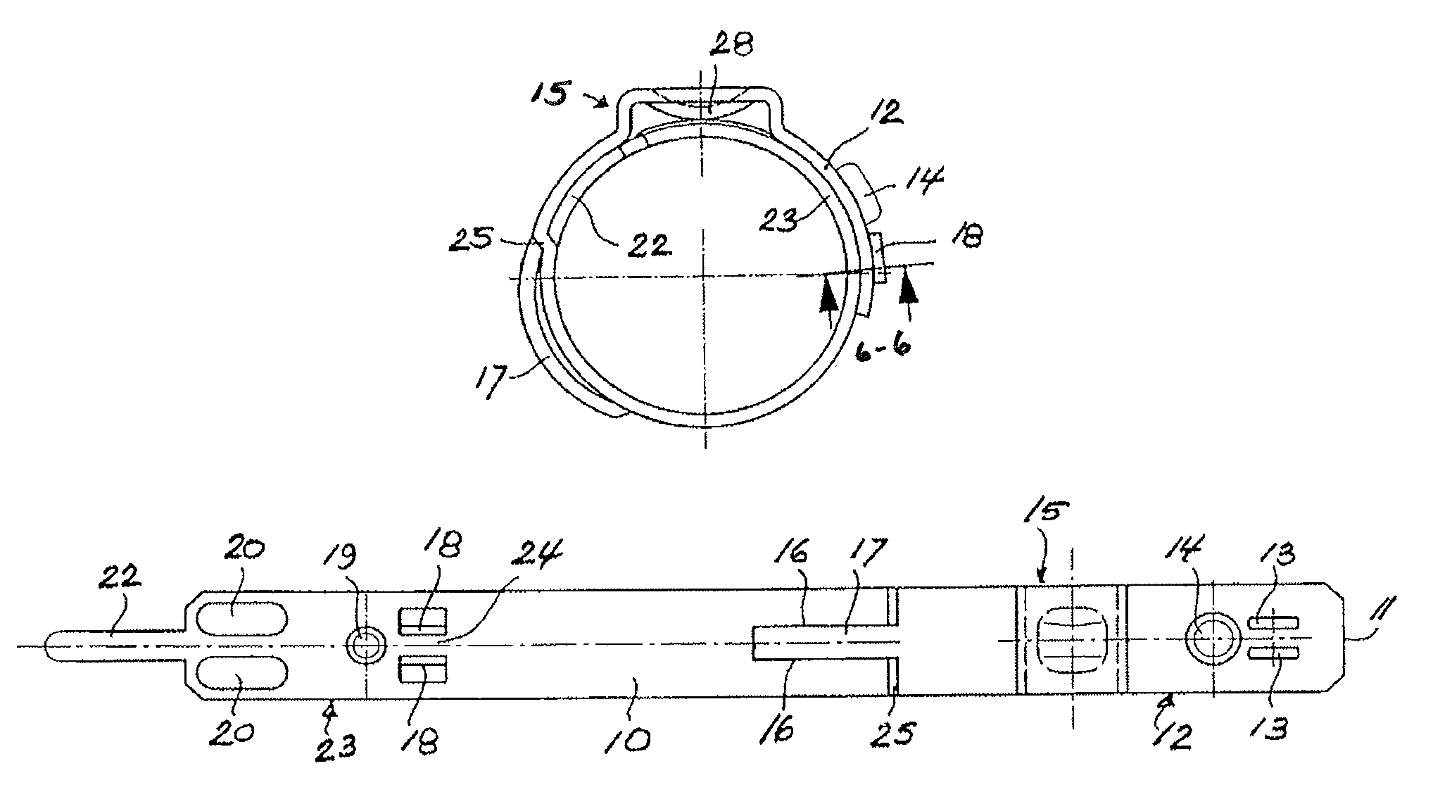
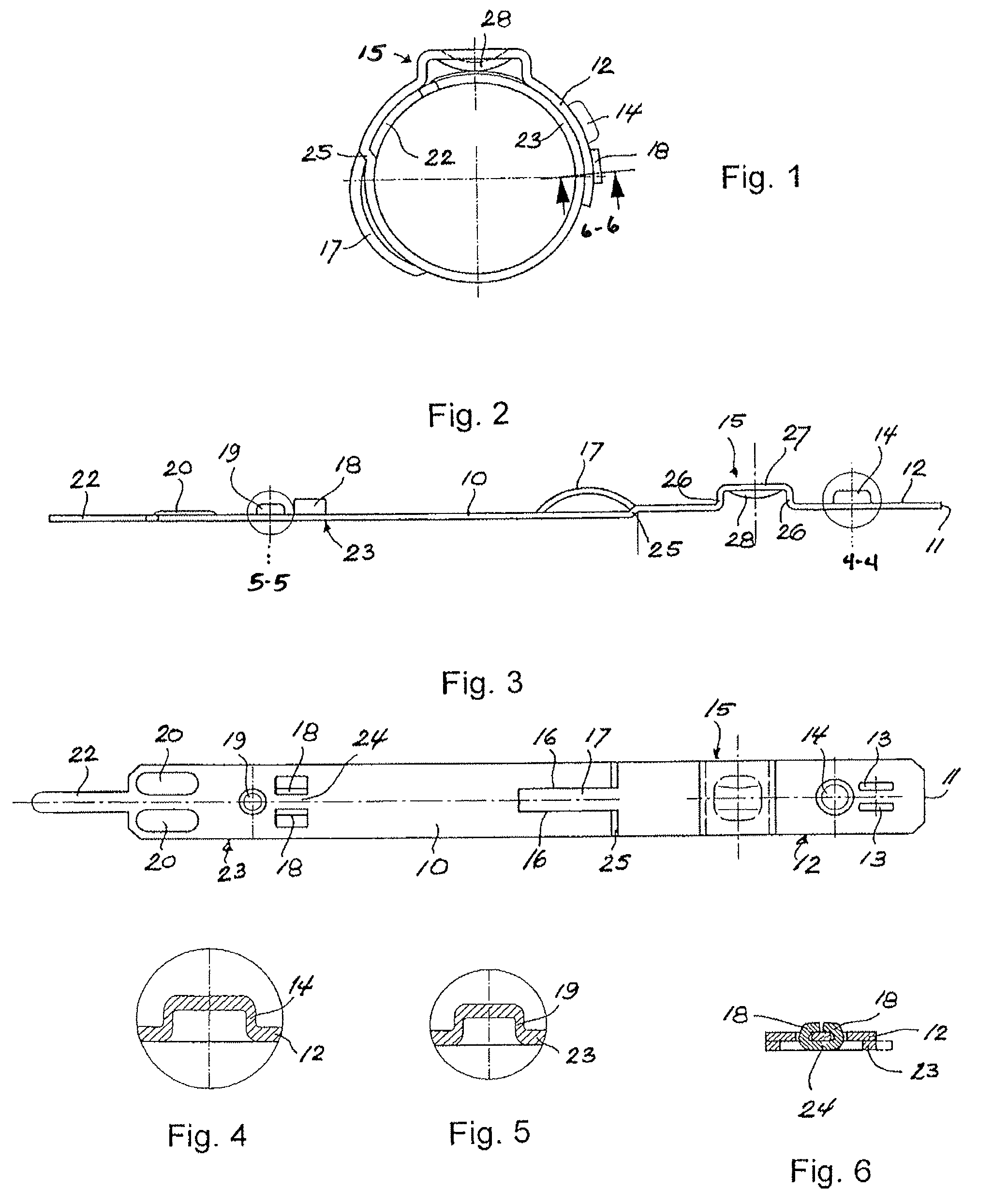
[0023]The hose clamp shown in FIGS. 1-6 is made from a steel band 10 having a width of 8 to 15 mm, typically 10 mm, and a band thickness of 0.6 to 1.0 mm, typically 0.8 mm. Starting from the free end 11 of the band end portion 12, which constitutes the outer band portion in the closed condition of the clamp shown in FIG. 1, the following structures are formed in the band 10: two parallel slots 13 extending in the longitudinal direction of the band 10; a cup-shaped embossment 14; an ear-shaped tightening means 15; a central band portion 17 later...


PUM


Abstract

A clamp is formed from a band with overlapping end portions. The clamp includes closing means including an aperture in one of the band end portions and a projection on the other band end portion to engage the aperture in a closed condition of the clamp and hold the mutually overlapping band end portions upon one another. The clamp also includes tightening means for tightening the clamp by reducing the circumferential length from the closed condition and a tightened condition. The clamp has force transmitting means for positively transmitting tensile force between the mutually overlapping band end portions in the tightened condition of the clamp. The force transmitting means includes a first cup-shaped embossment formed in one of the band end portions and a second cup-shaped embossment formed in the other band end portion and adapted to engage the first cup-shaped embossment in the closed condition of the clamp.

Description

CROSS-REFERENCE TO RELATED APPLICATION(S)[0001]This is a National Stage U.S. patent application that relies for priority on International Patent Application No. PCT / EP2006 / 004344, filed on May 9, 2006, the contents of which are incorporated herein by reference.FIELD OF THE INVENTION[0002]This invention relates to a hose clamp. More specifically, this invention relates to a hose clamp formed from a single band of material.BACKGROUND[0003]U.S. Pat. No. 5,305,499 discloses a clamp formed from a band. The open clamp, which in the delivery condition is circularly pre-shaped, is placed around the object to be clamped with the two band end portions overlapping one another. For closing the clamp, hooks are provided in the overlapped inner band end portion, which engage apertures provided in the outer band end portion. The clamp is subsequently tightened by narrowing a so-called “Oetiker ear”.[0004]The known clamp has three hooks. One of the hooks is a guide hook in the form of a tab bent fr...

Claims


Application Information

Patent Timeline
Patent Type & Authority Patents(United States)
IPC IPC(8): F16L33/00F16L33/025
CPCF16L33/025F16L33/035Y10T24/1478Y10T24/148Y10T24/1412Y10T24/1457F16L55/172
Inventor STREULI, WALTER
Owner OETIKER SCHWEIZ AG
Why Eureka
Try Eureka