
Open-centre valve block with two pump connections and associated auxiliary sliders on the main sliders

A technology for auxiliary sliders and main sliders, which is applied to servo motor components, fluid pressure actuators, earth movers/shovels, etc., can solve the problem that the unloading valve is not opened quickly enough, and achieves low cost and low cost. Avoid the formation of shrinkage cavity, the effect of low cost

Active Publication Date: 2015-06-10
ROBERT BOSCH GMBH
View PDF6 Cites 2 Cited by
  • Summary
  • Abstract
  • Description
  • Claims
  • Application Information

AI Technical Summary

Problems solved by technology

But the unloading valve also does not open fast enough to completely avoid pressure spikes

Method used


Image

  • Open-centre valve block with two pump connections and associated auxiliary sliders on the main sliders
  • Open-centre valve block with two pump connections and associated auxiliary sliders on the main sliders
  • Open-centre valve block with two pump connections and associated auxiliary sliders on the main sliders

Examples


Embodiment Construction

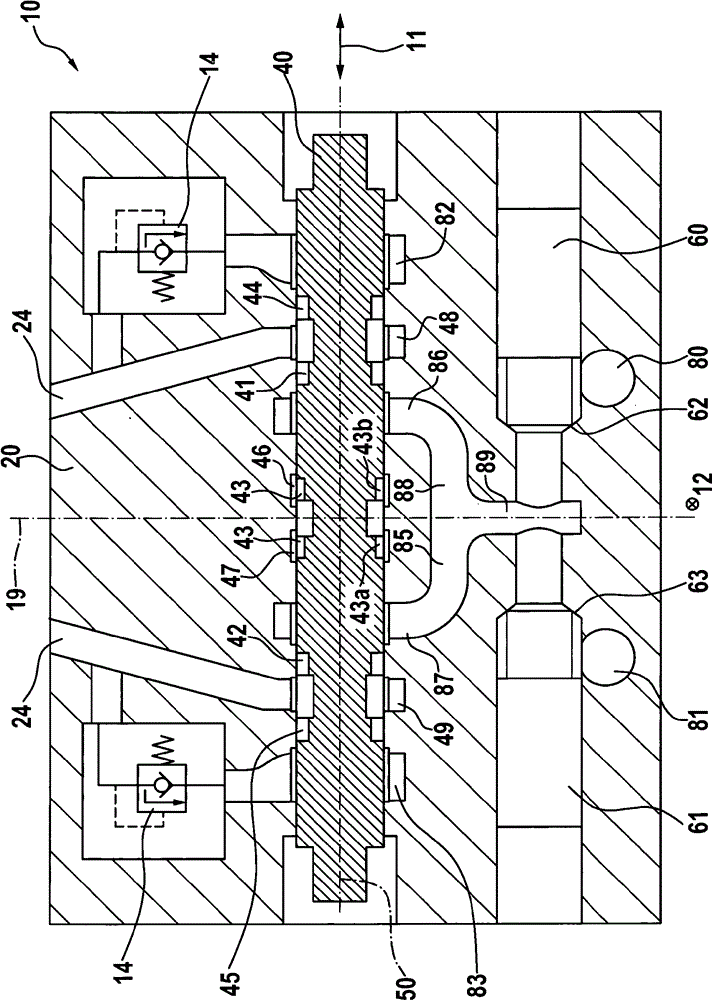
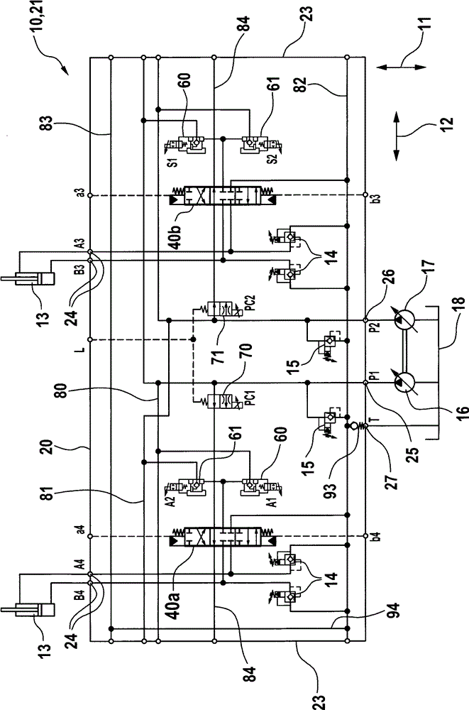
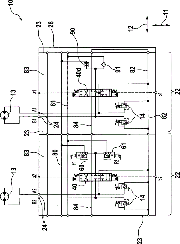
[0027] figure 1 A wiring diagram of the valve block 10 in the region of the base body 21 of the housing 20 is shown. The base body 21 is produced in one piece from cast iron in a casting method with a lost core. The basic body has two opposite, flat contact surfaces 23, the reference of the housing 20 figure 2 with 3 The described sub-body is added to the contact surface. The parallel contact surfaces 23 are oriented perpendicular to the longitudinal direction 12 .

[0028] The base body 21 has a first and a second pump connection 25 ; 26 and a tank connection 7 . A first and a second pump 16; 17 are connected to the pump connection 25; 26, the first and the second pump each having an adjustable displacement volume. The pump 16 ; 17 draws pressurized fluid, in particular hydraulic oil, from the tank 18 , wherein the pressurized fluid flows back into the tank 18 via the tank connection 27 .

[0029] The displacement volume of the pumps 16 : 17 can be adjusted hydraulical...


PUM


Abstract

The invention relates to a valve block (10) comprising a plurality of main sliders (40), which are supplied in parallel with pressure fluid via a first and a second pump conduit (80; 81), the fluid stream, which flows in from the respective pump conduits (80; 81), being controllable by means of an associated first and second auxiliary slider (60; 61). All main sliders (40) are surrounded by a first and a second annular groove (46; 47) in the housing (20) so as to form an adjustable third main aperture (43) that connects the first annular groove to the second annular groove (46; 47), the first annular groove (46) of a first main slider being connected to the first pump connection, the first annular groove (46) of a second main slider being connected to the second pump connection, the second annular groove (47) of a third and of a fourth main slider being connected to a tank connection on the housing (20), furthermore, the first annular groove (46) of a main slider (40) being connected to the second annular groove (47) of an adjacent main slider (40), the third main aperture (43) becoming smaller when the first or the second main aperture (41; 42) of the same main slider (40) becomes larger.

Description

technical field [0001] The invention relates to a valve block according to the preamble of claim 1 , which is especially intended for use in a hydraulic excavator. Background technique [0002] A valve block is known from EP 791 754 B1, which is provided for use in hydraulic excavators. The valve block comprises a housing in which for each consumer or each movement axis of the excavator a main slide movable linearly in the transverse direction is accommodated. In this case, the main slides are arranged side by side with respect to a longitudinal direction extending perpendicularly to the transverse direction. Arranged in the housing are a first pump channel and a second pump channel separate therefrom, which each extend substantially over the entire length of the housing. The first and second pump channels are connected via an associated first or second pump connection to an associated first or second pump, which has an adjustable displacement volume. [0003] Each main s...

Claims


Application Information

Patent Timeline
IPC IPC(8): E02F9/22F15B13/06F15B11/17
CPCE02F9/2242E02F9/2267E02F9/2282E02F9/2292E02F9/2296F15B11/17F15B13/06F15B2211/20576F15B2211/3059F15B2211/40515F15B2211/41509F15B2211/41518F15B2211/426F15B2211/45F15B2211/7142F15B2211/8606
Inventor E.黑姆斯柯克W.胡普E.里格尔W.福特
Owner ROBERT BOSCH GMBH
Learn More