Bone anchoring device

An anchoring device and anchoring technology, applied in the direction of fixator, internal fixator, internal bone synthesis, etc., can solve the problems of structural damage and increased rod surface wear, and achieve optimal load distribution, small wear, and avoid the risk of wear or damage. Effect

Inactive Publication Date: 2009-01-21
BIEDERMANN TECH GMBH & CO KG
View PDF2 Cites 3 Cited by
  • Summary
  • Abstract
  • Description
  • Claims
  • Application Information

AI Technical Summary

Problems solved by technology

In this case, there may be a risk that localized pressure peaks may lead to structural damage due to increased wear on the rod surfaces caused by the engaged structure

Method used


Image

  • Bone anchoring device
  • Bone anchoring device
  • Bone anchoring device

Examples


Embodiment Construction

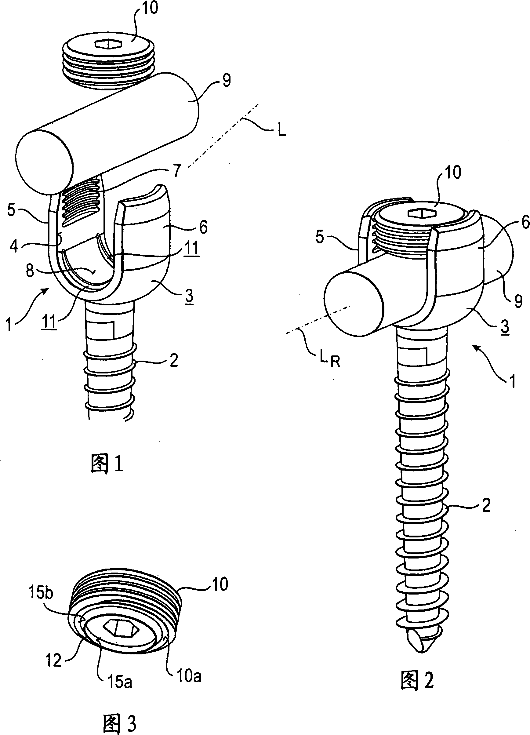
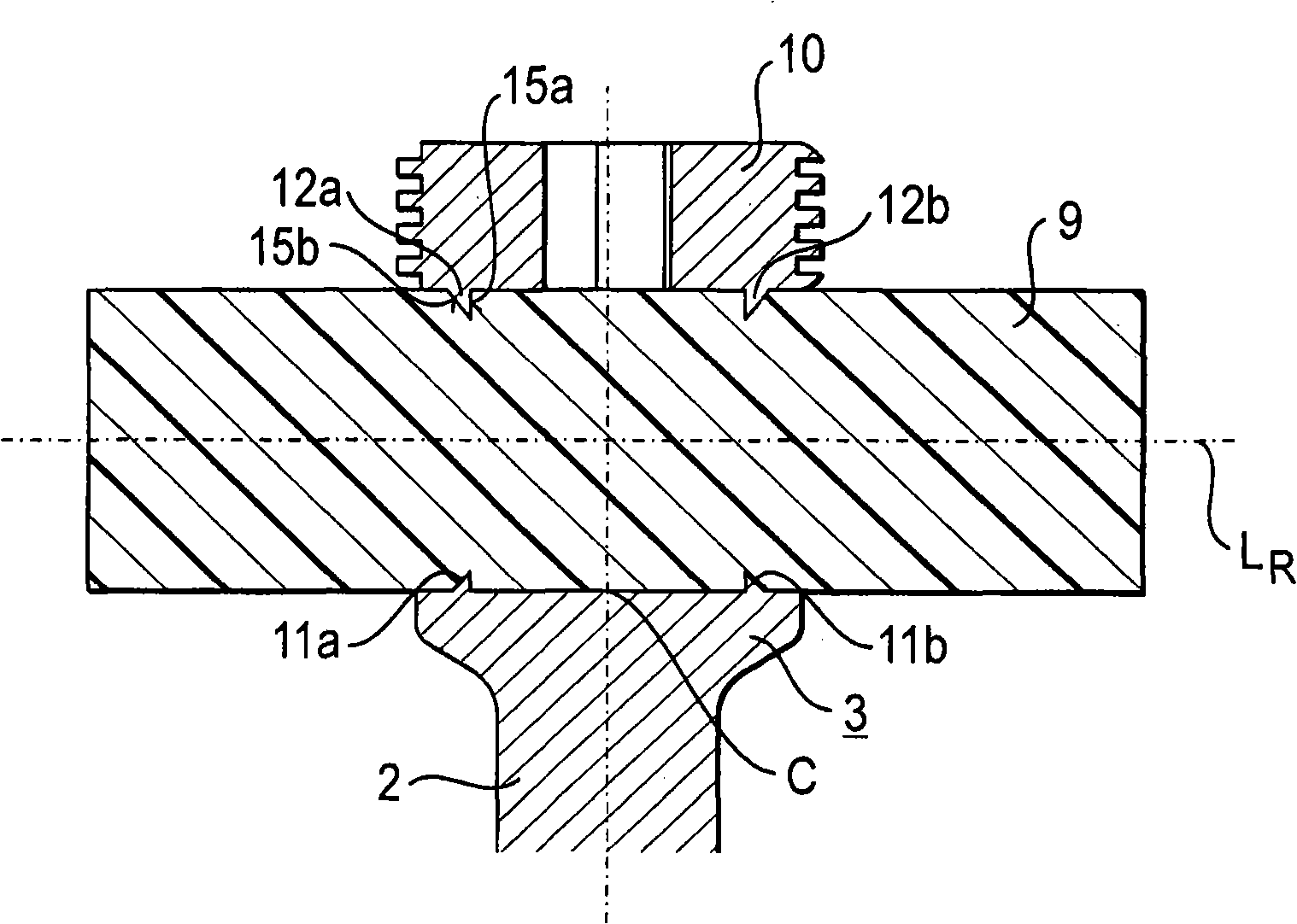
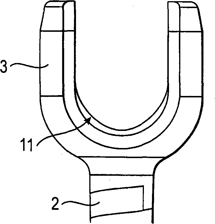
[0032] As shown in FIGS. 1 to 5 , the bone anchoring device according to the first embodiment includes a bone anchoring element 1 having an anchor rod 2 with a bone thread, a tip at one end, and a receiving portion 3 at the opposite end. The receiving part 3 is substantially cylindrical and comprises a substantially U-shaped groove 4 forming two free legs 5 , 6 . Internal threads 7 are provided on the legs. The bottom of the U-shaped groove forms a seat 8 for receiving a rod 9 . Rod 9 is used to connect multiple bone anchoring elements. To fix the rod 9 in the groove 4, a locking element in the form of an internal screw 10 that can be screwed between the legs 5, 6 is provided.

[0033] The rod 9 is made of a biocompatible elastic material, preferably plastic. In particular, the material is a free-flowing material. For example, the rod 9 is made of an elastomeric material based on polycarbonate-polyurethane or polycarbonate-urethane (PCU).

[0034] As can be seen in partic...


PUM


Abstract

A bone anchoring device is provided comprising an anchoring element having a shank (2) to be anchored in a bone or a vertebra, a rod (9) for connecting at least two anchoring elements, the rod being made of an elastic material, a receiving part (3) being connected to the shank (2) for receiving the rod, a seat (8) for the rod being provided in the receiving part the seat having a rod contacting surface, a locking device (10) cooperating with the receiving part for fixation of the rod in the seat, the locking device comprising a rod contacting surface, wherein the rod contacting surface of the seat and/or the rod contacting surface of the locking device comprises an engagement structure (11,12) for engaging the rod, the engagement structure having an asymmetric cross section.

Description

technical field [0001] The present invention relates to a bone anchoring device for dynamically stabilizing a bone, especially a bone anchoring device for dynamically stabilizing a spine. The bone anchoring device comprises a bone anchoring element connectable to a flexible rod made of elastic material. In order to fix the rod, an engagement structure is provided whose shape equalizes the pressure distribution on the rod in the fixed state. Background technique [0002] EP 1 759 646 A1 discloses a spinal implant for dynamic stabilization of the spine using flexible rods made of elastomeric material. The rod is fixed in the receptacle by means of locking means which clamp the rod by friction with an indirect form-fit contribution. [0003] EP 1 795 134 A1 discloses a polyaxial screw for use with a flexible rod made of elastomeric material. To secure or hold the rod in place, engaging formations are provided in the receptacle that receives the rod and on the locking means t...

Claims


Application Information

Patent Timeline
Patent Type & Authority Applications(China)
IPC IPC(8): A61B17/70
CPCA61B17/7032A61B17/7037A61B17/7035A61B17/7031A61B17/58A61B17/70
Inventor L·比德曼W·马蒂斯S·弗洛伊迪格
Owner BIEDERMANN TECH GMBH & CO KG
Why Eureka
Try Eureka