Hydraulic assembly comprising a variable displacement pump and a relief valve

A hydraulic system and servo pump technology, applied in servo motors, servo meter circuits, fluid pressure actuators, etc., can solve problems such as hydraulic system damage, problems, high pressure peaks, etc., to avoid pressure peaks and simply output pressure. , Save the effect of hydraulic pressure medium pipeline

Inactive Publication Date: 2012-10-03
ROBERT BOSCH GMBH
View PDF4 Cites 2 Cited by
  • Summary
  • Abstract
  • Description
  • Claims
  • Application Information

AI Technical Summary

Problems solved by technology

For average proc speeds this doesn't really matter, but at faster proc speeds it can cause problems
For example, for an actuating signal for reducing the delivery volume flow of a servo pump, the valve plug is moved into the desired position at a higher speed than the servo pump, which has only a lower delivery volume flow due to the delay, and thus Formation of high pressure peaks which can cause damage to the hydraulic system

Method used


Image

  • Hydraulic assembly comprising a variable displacement pump and a relief valve
  • Hydraulic assembly comprising a variable displacement pump and a relief valve
  • Hydraulic assembly comprising a variable displacement pump and a relief valve

Examples


Embodiment Construction

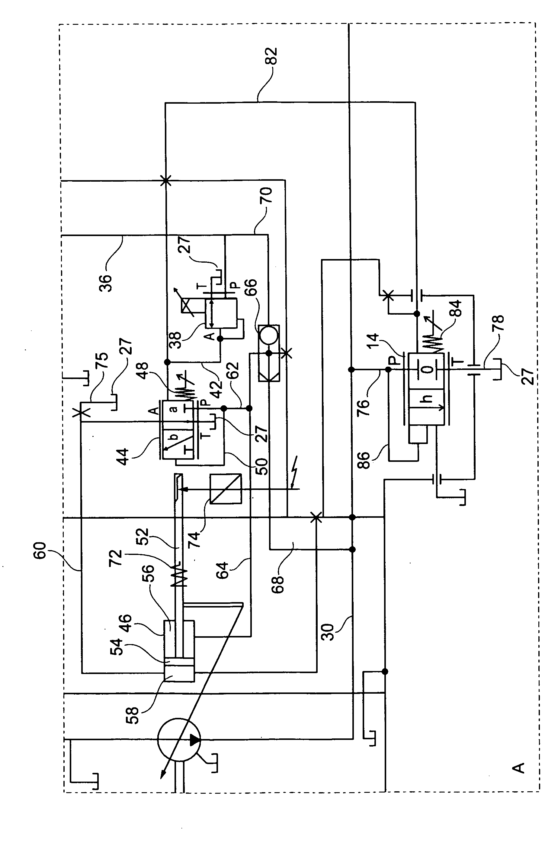
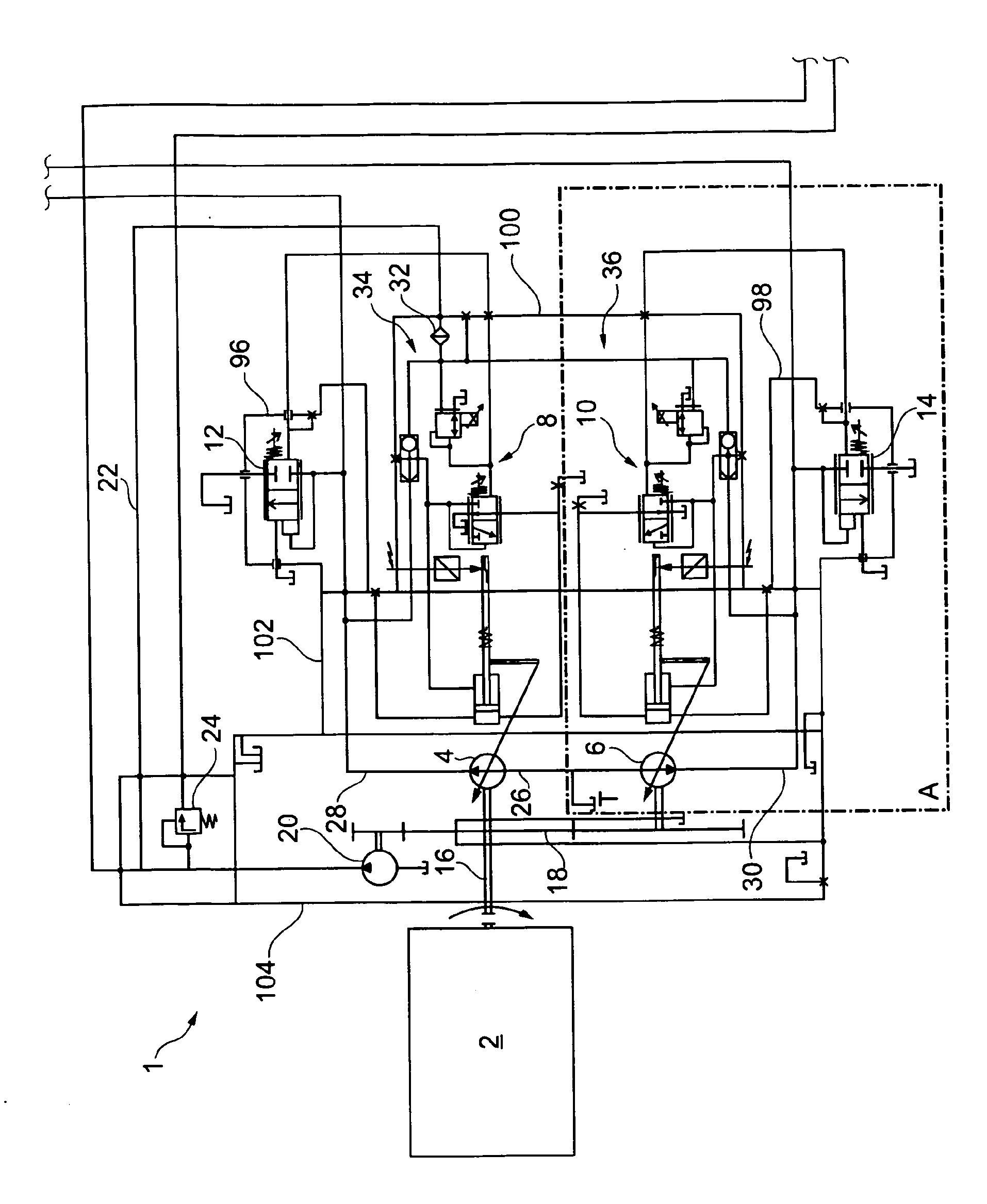
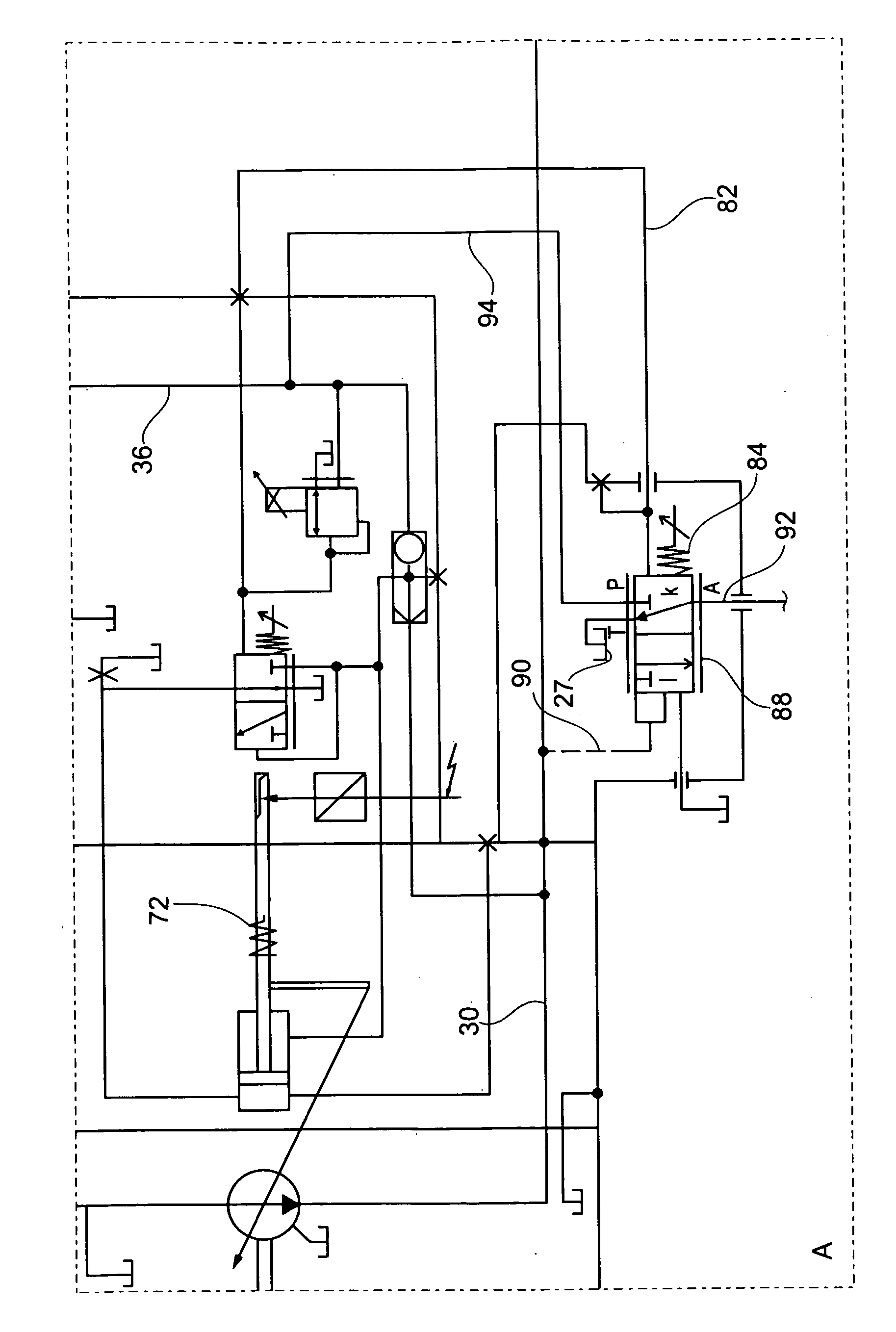
[0024] figure 1 According to the first embodiment, a schematic circuit diagram of the hydraulic system 1 according to the present invention is shown. The hydraulic system has two servo pumps or Verstell pumps 4, 6 driven by a drive unit 2 for supplying pump pressure or output pressure to a load not shown. The pump regulators 8, 10 are used to control the servo pumps 4, 6, respectively. In order to reduce the respective output pressure in relation to the pressure difference between the setpoint pressure and the output pressure, each servo pump 4 and 6 is equipped with a comparison valve or injection valve (Vergleichsventil) 12 or 14.

[0025] The servo pumps 4 and 6 have the same structure and hydraulic connection as the respective pump regulator 8 or 10 and the respective comparison valve 12 or 14 in terms of device technology. Therefore, for the sake of simplicity, the following main references are figure 1 The servo pump 6 shown below illustrates the hydraulic structure. In ad...


PUM


Abstract

The invention relates to a hydraulic assembly comprising at least one variable displacement pump (4, 6), which is set by a pump controller (8, 10) depending on a target pressure. The at least one variable displacement pump is used to supply at least one load with a pressure medium quantity. Furthermore, a comparison valve (12, 14) is provided, by means of which the outlet pressure is reduced to the target pressure starting at a certain pressure difference, which is to say, when the outlet pressure exceeds the target pressure by a predetermined value, the outlet pressure is lowered directly or indirectly by means of the comparison valve.

Description

Technical field [0001] The invention relates to a hydraulic system according to the preamble of claim 1. Background technique [0002] One such hydraulic system is disclosed in DE 10 2007 035 072 A1 of the applicant. Here, the servo pump and control block depend on the adjustment signal to trigger. The adjustment signal is transmitted hydraulically or electrically by, for example, a joystick operated by the operator through the control electronics to the control block and to the servo pump. Since the control electronics usually used in the hydraulic system of a motor vehicle has a certain processing time, and the pump regulator used to control the servo pump also needs a certain time to adjust the servo pump based on inertia, so when the servo pump is triggered Formed a time delay. This usually causes the servo pump to be triggered as a control block at another point in time. For the average trigger speed, this is not important, but it can cause problems when the trigger spee...

Claims


Application Information

Patent Timeline
Patent Type & Authority Applications(China)
IPC IPC(8): F15B11/05
CPCF15B11/055F15B2211/20553F15B2211/20576F15B2211/5157F15B2211/528F15B2211/50563F15B2211/50536F15B2211/253
Inventor E.赫姆斯柯克
Owner ROBERT BOSCH GMBH
Why Eureka
Try Eureka