Lubrication system and method configured for supplying pressurized oil to an engine

a technology of lubrication system and pressurized oil, which is applied in the direction of lubrication of auxiliaries, lubrication elements, pressure lubrication, etc., can solve the problems of reducing the output pressure, limiting the high-speed output flow capability, and unwanted nois

Active Publication Date: 2012-02-23
GM GLOBAL TECH OPERATIONS LLC
View PDF0 Cites 1 Cited by
  • Summary
  • Abstract
  • Description
  • Claims
  • Application Information

AI Technical Summary

Benefits of technology

[0004]A method of providing pressurized oil to an engine with a rotary pump and an eductor includes determining an operating characteristic of the engine. A solenoid valve is moved to one of a first position and a second position based on the operating characteristic of the engine. The solenoid valve supplies a fluid signal that allows pressurized oil to flow into an eductor when the solenoid valve is in the first position such that a volume of oil flowing from a sump and through the eductor to a rotary pump is increased. The solenoid valve does not supply a fluid signal and pressurized oil is prevented from entering the eductor when the solenoid valve is in the second position such that the volume of oil flowing from the sump and through the eductor to the rotary pump is not increased.

Problems solved by technology

Dissolved and entrained air in fluid pumped by a positive displacement pump reduces a pump's output flow capacity resulting in reduced output pressure and unwanted noise due to cavitation.
The presence of cavitation in a pump has the potential of severely limiting its high speed output flow capability.

Method used


Image

  • Lubrication system and method configured for supplying pressurized oil to an engine
  • Lubrication system and method configured for supplying pressurized oil to an engine
  • Lubrication system and method configured for supplying pressurized oil to an engine

Examples


Embodiment Construction

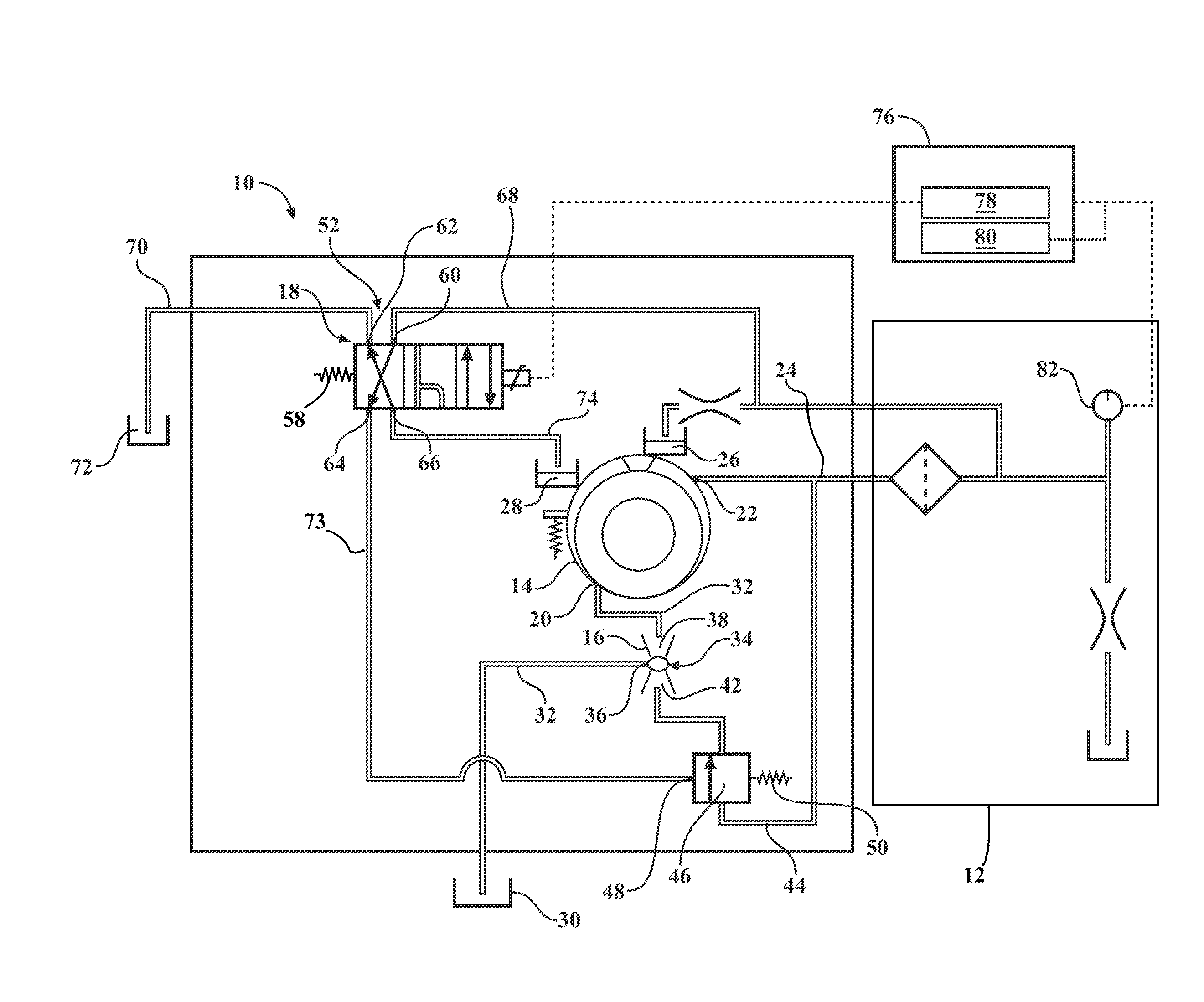
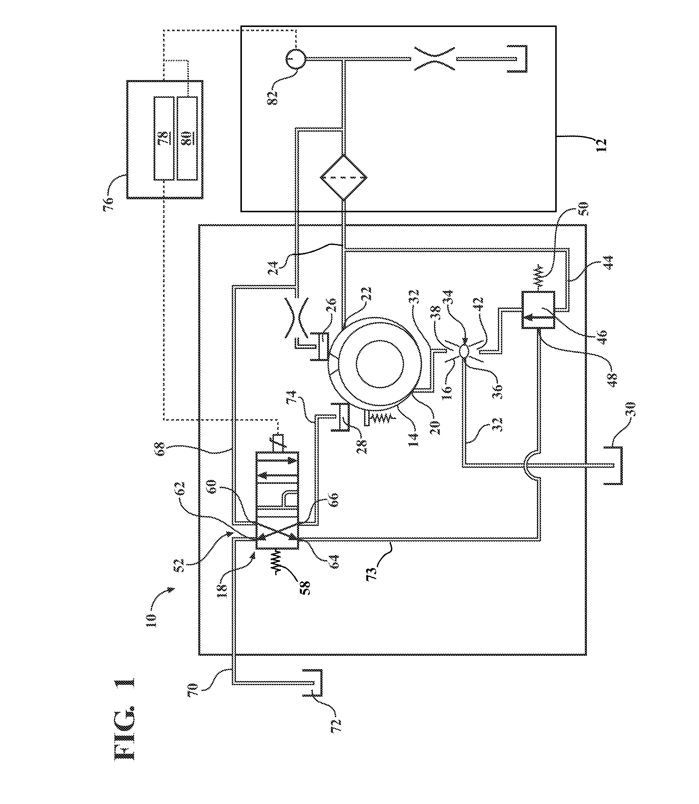
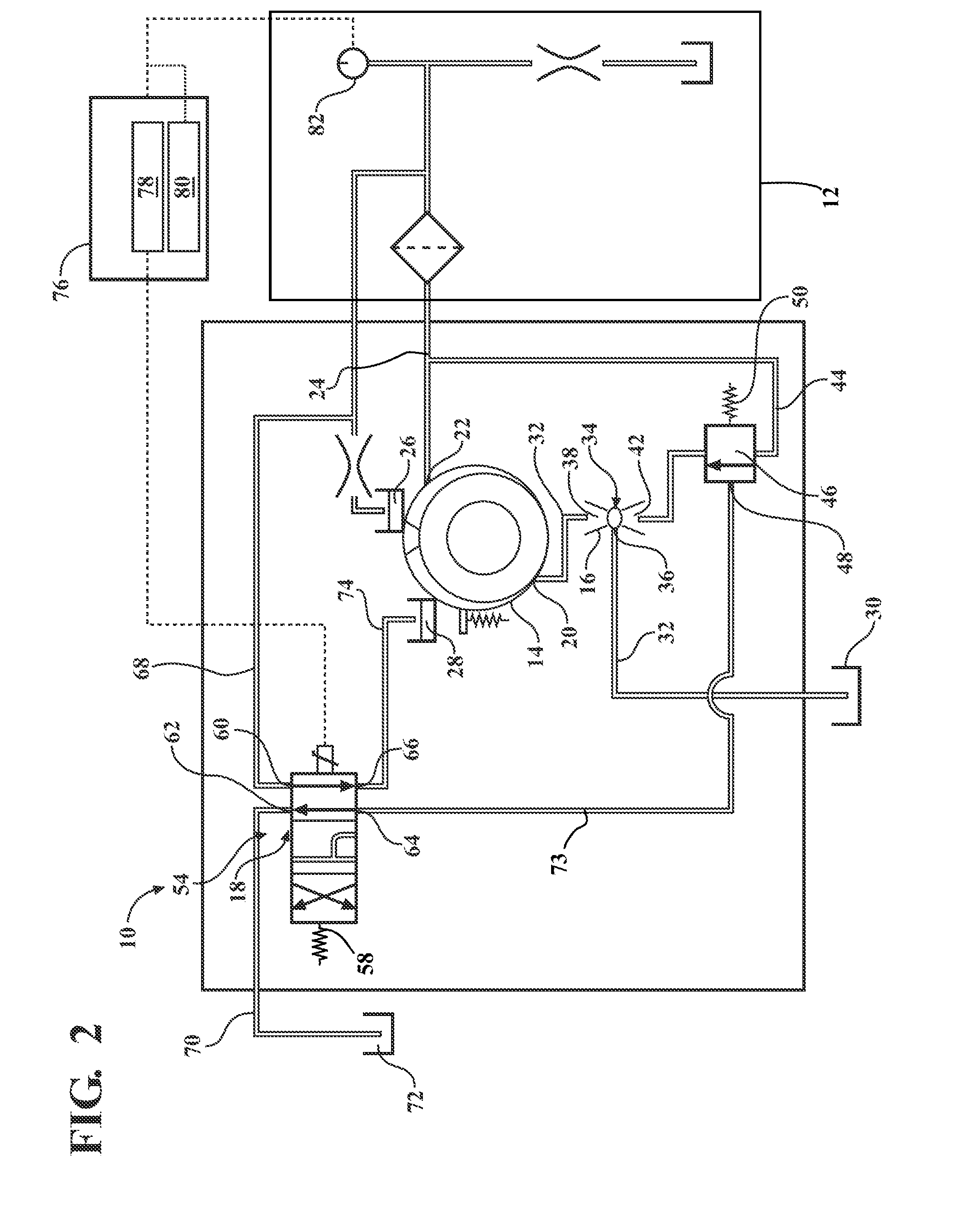
[0013]Referring to the drawings, wherein like reference numbers refer to like components, FIGS. 1-6 illustrate a lubrication system 10 that is configured to provide pressurized oil to an engine 12. The lubrication system 10 includes a rotary pump 14, an eductor 16, a solenoid valve 18, and a flow control valve 46. More specifically, the rotary pump 14 may be either a fixed or a variable displacement pump. The rotary pump 14 includes a primary intake port 20 and a supply port 22. The rotary pump 14 is operatively connected to the engine 12 such that rotation of the engine 12 also rotates the rotary pump 14 to generate oil flow to provide pressurized oil to the engine 12. The primary intake port 20 receives oil from the eductor16 as the rotary pump 14 rotates. The oil received from the eductor 16 is pressurized by the rotary pump 14. An oil output line 24 is fluidly connected to the supply port 22 of the rotary pump 14 and is configured to provide the pressurized oil from the rotary p...


PUM


Abstract

A lubrication system includes a rotary pump, an eductor, and a solenoid valve and is configured to provide pressurized oil to an engine. The rotary pump is configured to generate oil flow. A supplemental supply line selectively provides pressurized oil into the eductor. The solenoid valve is movable between a first position and a second position. The solenoid valve supplies a fluid signal that allows pressurized oil to flow from the supplemental supply line and into the eductor when the solenoid valve is in the first position to increase the volume of oil flowing from a sump of the engine into the rotary pump. When the solenoid valve does not supply a fluid signal, pressurized oil is prevented from entering the eductor and the volume of oil flowing from the sump and through the eductor to the rotary pump is not increased.

Description

TECHNICAL FIELD[0001]The invention relates to a lubrication system and method configured for supplying pressurized oil to an engine.BACKGROUND OF THE INVENTION[0002]Dissolved and entrained air in fluid pumped by a positive displacement pump reduces a pump's output flow capacity resulting in reduced output pressure and unwanted noise due to cavitation. Cavitation occurs when the entrained air collapses or implodes as it passes from a relatively low pressure region of a pump, such as a fluid inlet, to a relatively higher pressure region, such as a discharge or outlet region. The presence of cavitation in a pump has the potential of severely limiting its high speed output flow capability.SUMMARY OF THE INVENTION[0003]A lubrication system is configured to provide pressurized oil to an engine. The lubrication system includes a rotary pump, an eductor, and a solenoid valve. The rotary pump is configured to provide pressurized oil to the engine. The rotary pump includes a primary input por...

Claims


Application Information

Patent Timeline
Patent Type & Authority Applications(United States)
IPC IPC(8): F01M1/02
CPCF01M2001/0238F01M1/16
Inventor STALEY, DAVID R.SCHULTZ, JOHN C.
Owner GM GLOBAL TECH OPERATIONS LLC
Why Eureka
Try Eureka