Lighting device

A lighting device and light source technology, which is applied in the direction of lighting devices, independent lighting devices, lighting device components, etc., can solve problems such as reducing brightness, and achieve the effect of reducing brightness and reducing illuminance spots

Inactive Publication Date: 2011-11-09
TWINBIRD CORP
View PDF5 Cites 1 Cited by
  • Summary
  • Abstract
  • Description
  • Claims
  • Application Information

AI Technical Summary

Problems solved by technology

[0005] The purpose of the present invention is to solve the above problems and p

Method used


Image

  • Lighting device
  • Lighting device
  • Lighting device

Examples


Example Embodiment

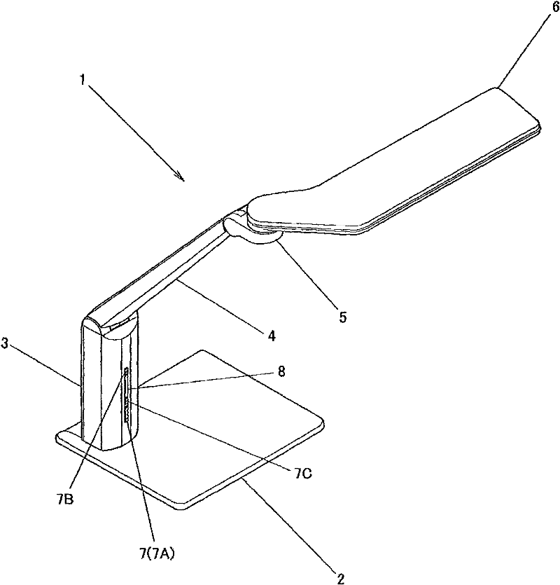
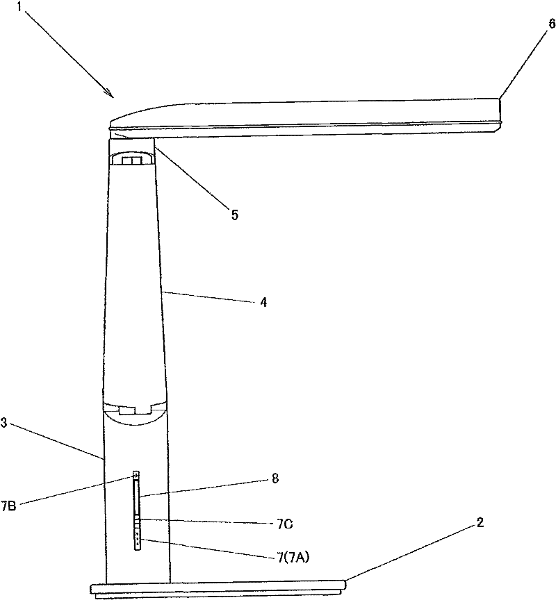
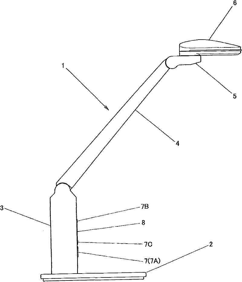
[0033] Below, according to Figure 1 to Figure 7 The embodiments of the present invention will be described. Numeral 1 is a desk lamp as an example of a lighting device. The structure of the desk lamp 1 includes: a bottom part 2; a columnar part 3 fixed on the bottom part 2; an arm part 4 movably arranged relative to the columnar part 3; a head part 5 movably arranged relative to the arm part 4 ; And the lamp 6 can be set movably relative to the head 5. In addition, an operation portion 7 and a display portion 8 are provided on the front side of the columnar portion 3. In addition, the above-mentioned operation unit 7 is composed of a main switch 7A and adjustment switches 7B and 7C. In addition, the display unit 8 is provided with a plurality of display LEDs (not shown).

[0034] The optical system of the above-mentioned lamp 6 is described in detail as follows. The lamp 6 has an LED 9 for lighting as a light source. The LED9 can be regarded as a small area surface light s...


PUM


Abstract

The invention provides a lighting device which can reduce brightness without reducing illumination, and comprises a light-guiding body (12) which can guide light (L) from an LED (() to a predetermined direction. The light-guiding body includes a reflecting surface (17) reflecting light from the LED (9) to a predetermined direction and an emitting surface (8) emitting light reflected by the reflecting surface. The reflecting surface (17) is composed by a plurality of reflecting faces (19) which are divided up and down. A step portion (20) is formed by offsetting at the direction of an optical axis (A) in a manner that the lower the reflecting faces (19) are disposed, the more distance the reflecting faces will be away from the LED (9). The light reflected by each reflecting face passes through the emitting surface with an interval of the quantity of each step portion through making each reflecting face to be uncontinuous. As the light of the emitting surface expands through areas and the light sum does not change, the light illumination will not be reduced and the brightness will be declined, enabling the illuminating objects to be easily seen in an operation area.

Description

technical field [0001] The present invention relates to lighting devices such as desk lamps. Background technique [0002] Illuminating devices such as desk lamps have been known for a long time. Furthermore, in recent years, as such an illuminating device, there is an illuminating device using a light-emitting diode (hereinafter, simply referred to as LED) as a light source (for example, refer to Patent Document 1: Japanese Patent Application Laid-Open No. 2008-123863). Such lighting devices using LEDs tend to increase because of the advantages of low power consumption and the ability to reduce the size of the main body of the lighting device. [0003] Such a lighting device is configured to illuminate the lower side of the lighting device main body. Therefore, when such a lighting device is used on a desk, it is necessary to arrange the lighting device main body directly above the user's work area. However, in this way, if the lighting device main body is located direct...

Claims


Application Information

Patent Timeline
IPC IPC(8): F21S6/00F21V13/00F21Y101/02
CPCF21S6/003F21Y2101/02F21Y2115/10
Inventor 大野彻田上松美
Owner TWINBIRD CORP
Why Eureka
Try Eureka