
Projection device

A projection device and lens technology, applied in projection devices, optics, instruments, etc., can solve problems such as eye and cervical vertebra fatigue

Inactive Publication Date: 2011-11-09
HONG FU JIN PRECISION IND (SHENZHEN) CO LTD +1
View PDF0 Cites 6 Cited by
  • Summary
  • Abstract
  • Description
  • Claims
  • Application Information

AI Technical Summary

Problems solved by technology

However, when the user is lying down, the user's field of view is approximately perpendicular to the optical axis direction of the lens. Therefore, the user needs to raise his head so that the field of view faces the optical axis direction of the lens to watch the projection. This will cause extreme fatigue to the user's eyes and cervical spine in the long run

Method used


Image

  • Projection device
  • Projection device
  • Projection device

Examples


Embodiment Construction

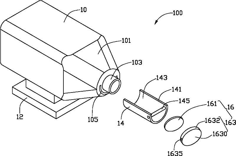
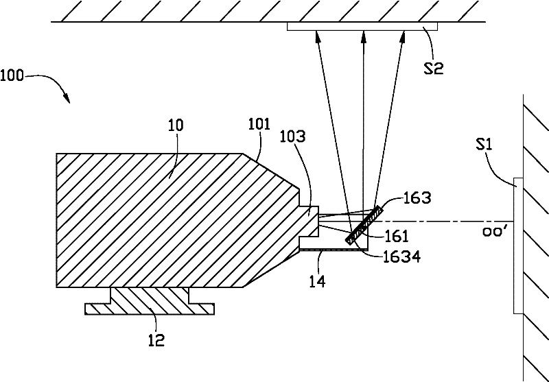
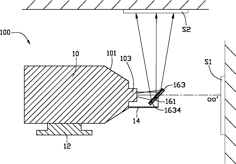
[0029] Please also refer to figure 1 and figure 2 , which is a perspective view of the projection device 100 in a preferred embodiment. The projection device 100 includes a body 10 , a base 12 , a movable frame 14 and an optical component 16 .

[0030] The base 12 is placed on a support surface (not shown in the figure, such as a desktop) supporting the projection device 100 , and the base 12 is used to support the fuselage 10 .

[0031] The fuselage 10 is fixed on the base 12 and is lifted by the base 12 away from the supporting surface, so that the fuselage 10 has a better heat dissipation effect. The fuselage 10 is substantially in the shape of a cuboid and includes a front end 101 . The front end 101 is provided with a lens 103 , and the light beam inside the body 10 can be projected through the lens 103 to be imaged in the first imaging area S1 . The lens 103 has an optical axis OO', and in this embodiment, the first imaging area S1 is substantially perpendicular to ...


PUM


Abstract

The invention relates to a projection device which comprises: an optical assembly, a body and a camera lens arranged on the body. Internal light beams of the body are projected through the camera lens so as to form an image in a first imaging area. The optical assembly is detachably arranged on a light path of the camera lens so as to reflect the light beams projected by the camera lens and to make the reflection light beams to form the image in a second imaging area. The first imaging area is intersected with the second imaging area. In the projection device, the light path of the light beam projected by the camera lens is changed by the optical assembly which is arranged on the light path of the camera lens so that the imaging of the projection device can switch between the first imaging area and the second imaging area. Furthermore, a projection direction of the projection device can be changed.

Description

technical field [0001] The invention relates to a projection device. Background technique [0002] With the continuous improvement of people's living standards, household projection devices (such as home theaters) have begun to emerge in the market. The projection device generally projects in the direction of the optical axis of the lens of the projection device, and the user's field of view needs to face the direction of the optical axis of the lens. Many users who like casual family life often like to sit and watch the projection sometimes, and sometimes like to lie down and watch the projection to enjoy the fun brought by the home theater. However, when the user is lying down, the user's field of view is approximately perpendicular to the optical axis direction of the lens. Therefore, the user needs to raise his head so that the field of view faces the optical axis direction of the lens to watch the projection. This will cause extreme fatigue to the user's eyes and cerv...

Claims


Application Information

Patent Timeline
Patent Type & Authority Applications(China)
IPC IPC(8): G03B21/00G03B21/28G02B26/08
Inventor 戴龙
Owner HONG FU JIN PRECISION IND (SHENZHEN) CO LTD
Learn More