Imaging equipment with upper photosensitive drum

A technology of imaging equipment and photosensitive drum, which is applied to the equipment, optics, and electric recording technology of applying charge pattern, etc., can solve the problems of wear, increase the contact pressure between the photosensitive drum and the developing roller, etc. Achieve the effect of increasing service life and reducing wear and tear

Active Publication Date: 2011-11-09
AVISION PRECISION IND (SUZHOU) CO LTD
View PDF4 Cites 0 Cited by
  • Summary
  • Abstract
  • Description
  • Claims
  • Application Information

AI Technical Summary

Problems solved by technology

[0004] In addition, when the imaging unit is installed on the base, there is also a buckle mechanism between the base and the imaging unit, which will also increase the contact pressure between the photosensitive drum and the imaging roller, causing further wear problems

Method used


Image

  • Imaging equipment with upper photosensitive drum
  • Imaging equipment with upper photosensitive drum
  • Imaging equipment with upper photosensitive drum

Examples


Embodiment Construction

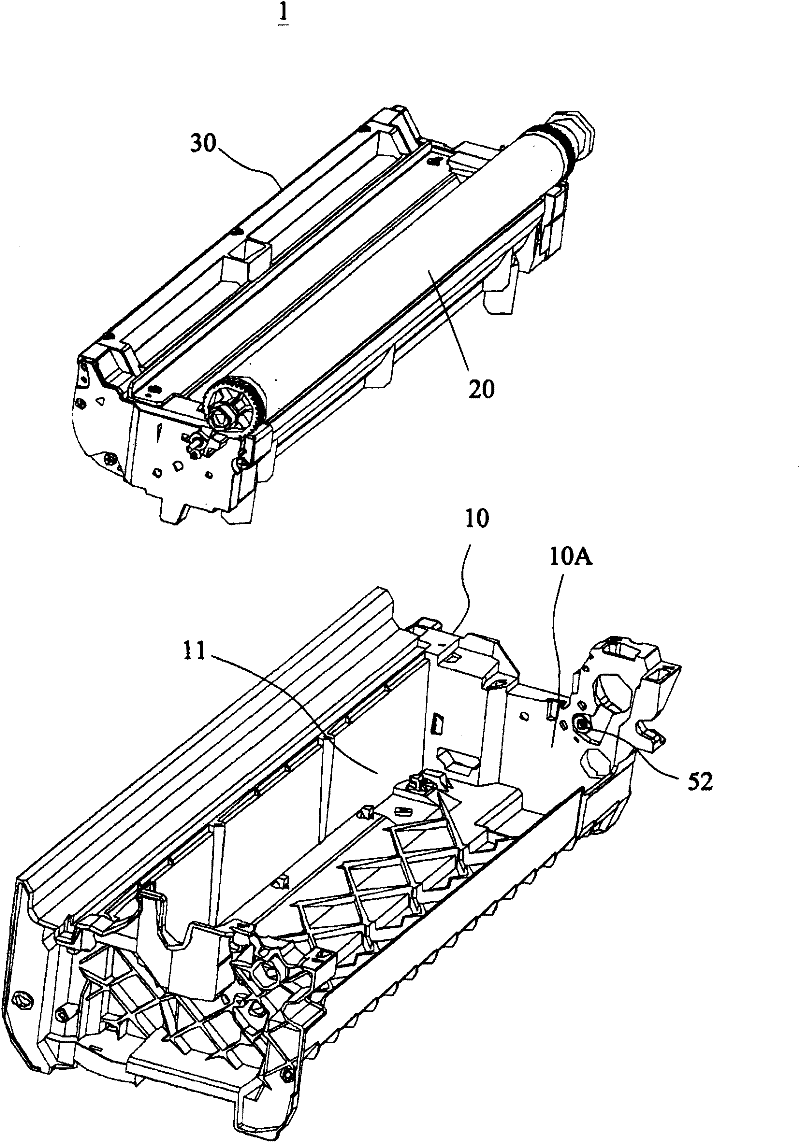
[0032] figure 1 An exploded perspective view of an imaging device 1 according to a preferred embodiment of the present invention is shown. Such as figure 1 As shown, the imaging device 1 of this embodiment includes a base 10 , a photosensitive drum 20 and a developing assembly 30 . The photosensitive drum 20 is mounted on a developing assembly 30 . The imaging component 30 is accommodated in the accommodating groove 11 of the base 10 . The roller 52 is rotatably mounted on a sidewall of the receiving groove 11 of the base 10 .

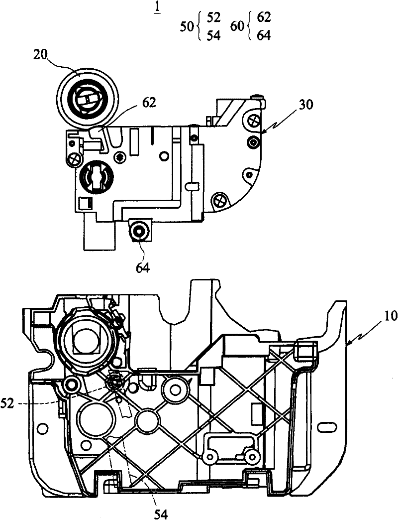
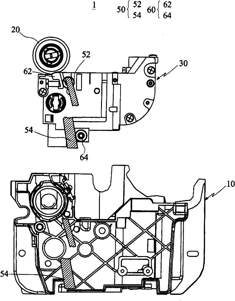
[0033] figure 2 An exploded side view of an imaging device 1 according to a preferred embodiment of the present invention is shown. Such as figure 2 As shown, the roller 52 is blocked by the base 10 and shown in dashed lines. In order to prevent the base 10 from blocking the mechanism features of the imaging assembly 30, the unnecessary part of the base 10 is cut off below, leaving only the part corresponding to the supporting assembly group 5...


PUM


Abstract

The invention discloses imaging equipment which comprises a base, a photosensitive drum, a developing component and an elastic component, wherein the developing component is movably arranged on the base and comprises a developing box and a developing roller; the developing roller is arranged on the developing box, is arranged opposite to the photosensitive drum and is contacted with the photosensitive drum so as to attach carbon powder to the photosensitive drum; the elastic component is arranged between the developing box and the base; and elastic force generated by the elastic component resists weight of the developing box and pushes the developing roller to the photosensitive drum.

Description

technical field [0001] The invention relates to an imaging device with an upper-mounted photosensitive drum, in particular to an imaging device with an upper-mounted photosensitive drum that can reduce the loss of the photosensitive drum. Background technique [0002] The bottom-mounted or side-mounted photosensitive drum of a traditional printer will bear the weight or lateral buckle force of the imaging assembly containing the toner cartridge, which will cause great friction loss when the photosensitive drum contacts the imaging roller of the toner cartridge , thus accelerating the consumption rate of the photosensitive film on the surface of the photosensitive drum, thereby shortening the life of the photosensitive drum. [0003] Since the toner cartridge contains toner, the amount of toner will decrease as the number of prints increases, resulting in a reduction in the weight of the toner cartridge. Due to the need to maintain the close contact between the developing ro...

Claims


Application Information

Patent Timeline
IPC IPC(8): G03G15/00
Inventor 阙壮华
Owner AVISION PRECISION IND (SUZHOU) CO LTD
Why Eureka
Try Eureka