Probe connector

一种连接器、探针的技术,应用在连接、测试/测量连接器、两部件连接装置等方向,达到接触压力均匀化、减少接触阻力变化的效果

Inactive Publication Date: 2011-11-09
MOLEX INC
View PDF1 Cites 28 Cited by
  • Summary
  • Abstract
  • Description
  • Claims
  • Application Information

AI Technical Summary

Problems solved by technology

Therefore, for example, when the coaxial plug 961 is inserted into or unplugged from the probe 851, the probe 851 may be displaced or moved relative to the movable plate 802.

Method used


Image

  • Probe connector
  • Probe connector
  • Probe connector

Examples


Embodiment Construction

[0047] While the present disclosure is capable of embodiments in different forms, only particular embodiments are shown in the drawings and will be described in detail herein, it is to be understood that the present disclosure is to be considered as exemplary of the principles of the disclosure, and It is not intended to limit the disclosure to what has been set forth. In the embodiments set forth herein, words used to explain the structure and direction of movement of the various elements of the present disclosure, such as up, down, left, right, front, back, and the like, are not absolute but relative . When the element is in figure 2 These terms apply when indicated. However, if the description of the location of an element changes, it is assumed that these words will change accordingly.

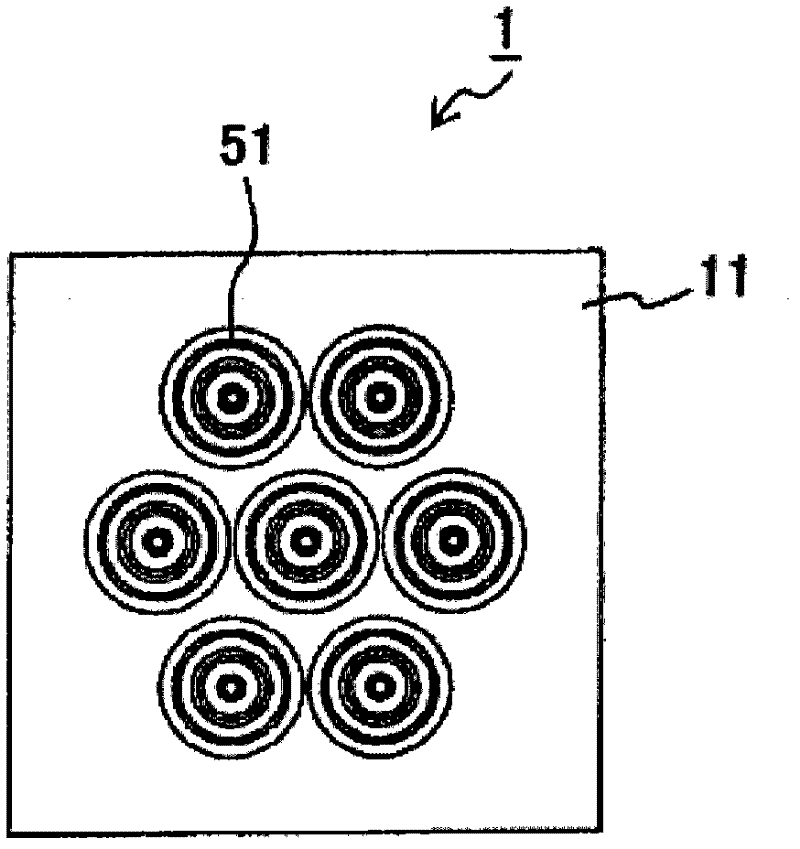
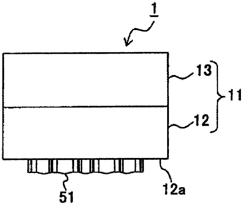
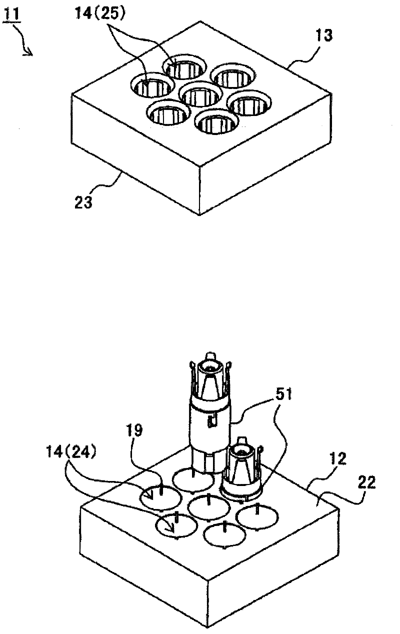
[0048] Figure 1-4 Each figure in shows the probe connector 1 of the embodiment. figure 1 is the front view of probe connector 1, while figure 2 is a side view of the probe connect...


PUM


Abstract

The invention refers to a probe connector (1) which connects a circuit board (2) and a coaxial plug (3) including an axial terminal (162) and a surrounding terminal(163). A coaxial probe (51) of the probe connector includes a center terminal (52) connected to the circuit board and the axial terminal, and an outer terminal (61) coaxial with the center terminal and connected to the circuit board and the surrounding terminal. The outer terminal includes an cylindrical outer conductor (62) surrounding the center terminal and mated with the surrounding terminal; an anchor (63) formed, as a projection(69), on part of an outer surface of the outer conductor by machining process so that a hole is formed on the part of the outer surface; and a conductive cover (91) covering and closing the hole and electrically conducted to the outer conductor. Thus, the position of the coaxial probe is slightly shifted even when the coaxial plug is inserted thereto or pulled therefrom.

Description

technical field [0001] The present disclosure relates generally to a probe connector, and more particularly, to a connector in which the position of the coaxial probe is slightly shifted when a coaxial plug is inserted into or unplugged from the coaxial probe. Misplaced or misaligned probe connectors. Background technique [0002] Japanese Utility Model Application No. 60-123666 purports to disclose a coaxially movable contact probe 851 used in a testing device, as shown in FIG. 16 . The coaxially movable contact probe 851 comprises a central conductor 852 and an outer conductor 861 having a generally cylindrical shape and surrounding the central conductor 852 . As shown in FIG. 17, the probes 851 are held by a movable plate 802 that is movable relative to an inspection target circuit board 801 on which an inspection target integrated circuit ("IC") is mounted. Also, a coaxial connector (“coaxial plug”) 961 is connected to one end of the probe 851 . Each coaxial plug 961 ...

Claims


Application Information

Patent Timeline
Patent Type & Authority Applications(China)
IPC IPC(8): H01R12/71H01R13/24G01R1/067G01R1/04H01R13/658H01R13/17H01R24/54
CPCH01R13/17G01R1/06772H01R12/714H01R13/2421H01R2201/20G01R1/06722G01R1/0416H01R12/71H01R13/24G01R1/067
Inventor 上坂廖水村晶范詹姆斯·马罗尼
Owner MOLEX INC
Why Eureka
Try Eureka