Aerated concrete cutting machine

A kind of technology of aerated concrete and cutting machine, applied in the direction of ceramic forming machine, manufacturing tools, etc., can solve the problems of unreasonable structure, low efficiency, unfavorable control, etc., and achieve the effect of compact and simple structure, small space occupation and high cutting precision

Inactive Publication Date: 2011-11-16
常州力顿机械科技有限公司
View PDF6 Cites 44 Cited by
  • Summary
  • Abstract
  • Description
  • Claims
  • Application Information

AI Technical Summary

Problems solved by technology

At present, although some cutting machines have improved the original ones that are large in size, bulky, and unreasonable in structure, such as using a lifting rod with a guide sleeve or guide rail to guide the vertical cutting device to move up and down, through the motor, reducer, rack and pinion, etc. The horizontal cutting device and the vertical cutting device are driven by transmission or chain transmission, and the turning table is used to turn over the green body. Compared with the cutting machine before the improvement, the existing cutting machine has simplified structure, reduced height and improved cutting accuracy. improve
But the cutting machine commonly used at present still has deficiencies, one is: the concrete body is hoisted from the steam curing car by driving, and the platform is turned over from the front after overturning the cutting machine body. Manual alignment is required, which is not conducive to control during positioning; second: during the lifting process, the cross-cutting frame of the vertical cutting device needs to cross the gap formed by the movement route of the horizontal cutting device to prevent the two from interfering with each other at the intersection of motion. The method of this gap is: set the upper and lower gears and the intermediate idler gear that run synchronously and in the same direction on the cross-cutting frame, and set the corresponding upper rack and lower rack on the column of the cutting machine frame. The center distance of the gear is greater than the height of the spanning gap. Driven by the driving device, the upper and lower gears mesh with the corresponding upper and lower racks respectively to drive the cross-cutting frame up and down; or set a gear on the cross-cutting frame, A movable rack is set at the position of the gap, and the cross-cutting frame crosses the gap by moving between the upper and lower racks. However, the lifting method of the above-mentioned cross-cutting frame spanning the gap is complicated in structure, and it is troublesome in terms of manufacturing and installation. The effect is not ideal, and the cumulative error generated after the gear is used has a greater impact on the accuracy of the movement
Third: After the aerated concrete body is cut horizontally and vertically according to the specifications by the cutting machine, it is turned back to the initial position before cutting by the turning table. At this time, although the edge materials on the front and rear sides of the body have been cut, they still stick Knot on the body, the traditional method is to use manual cleaning, use a scraper to scrape off the edge waste, the operation is cumbersome, the efficiency is low, the work intensity of the workers is high, and the environmental sanitation is affected; the fourth is: the traditional way of pushing and turning the turning table is Push the middle of the turning shaft directly by the oil cylinder to make the turning table turn over, which brings a lot of inconvenience to the support of the pushing oil cylinder, equipment foundation, maintenance and site cleaning, and cannot meet the requirements of production automation

Method used


Image

  • Aerated concrete cutting machine
  • Aerated concrete cutting machine
  • Aerated concrete cutting machine

Examples


Embodiment Construction

[0026] The present invention will now be further described in conjunction with the accompanying drawings and preferred embodiments. These drawings are all simplified schematic diagrams, which only illustrate the basic structure of the present invention in a schematic manner, so they only show the configurations related to the present invention.

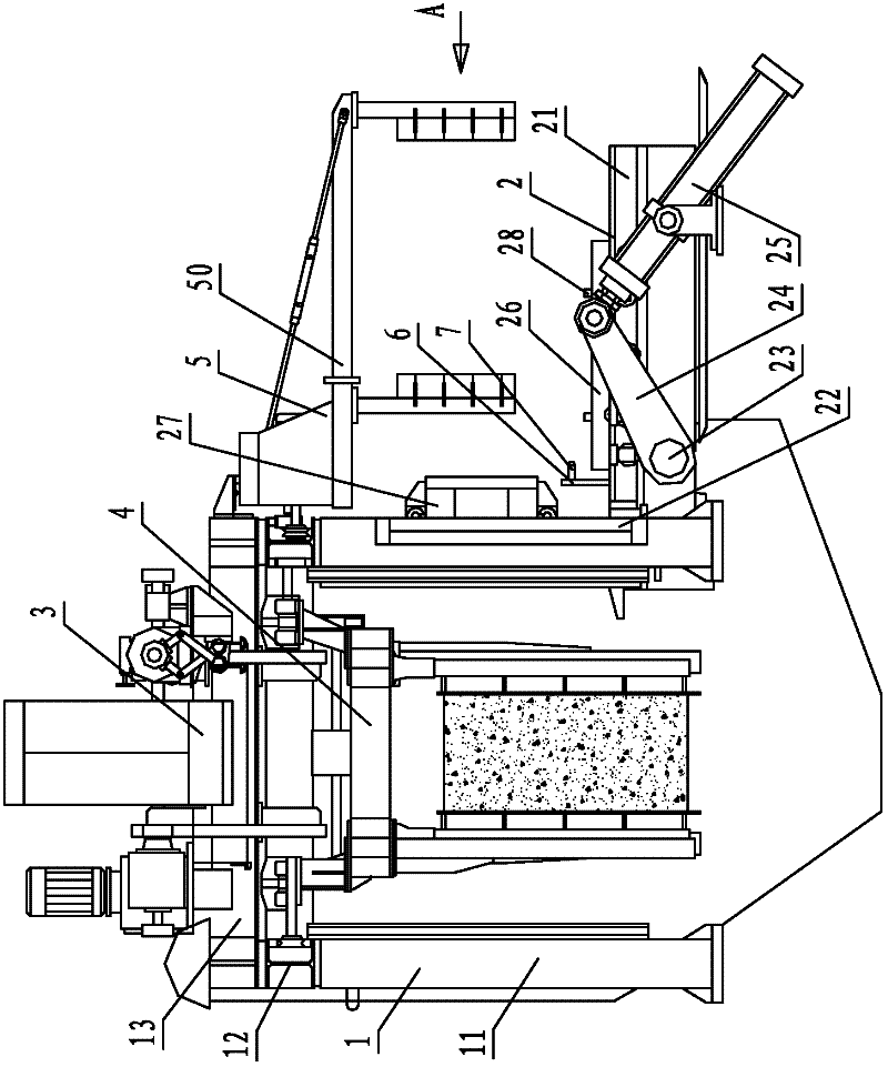
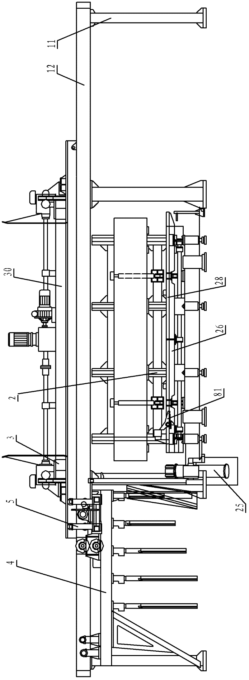
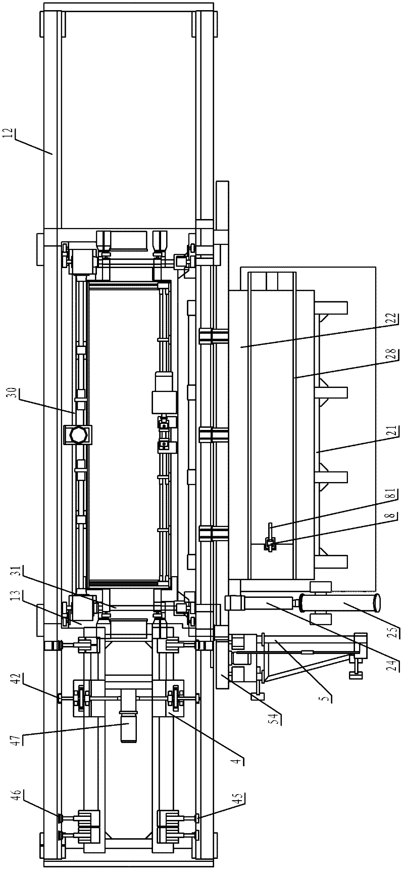
[0027] Such as figure 1 , figure 2 , image 3 The shown aerated concrete cutting machine includes a frame 1, and the frame 1 consists of two rows of four columns 11 in total, and two I-shaped beams 12 erected on the two rows of columns 11. It is composed of a beam 13 located above the two columns 11 in the middle and fixed to the girder 12. A turning platform 2 is provided in the middle of the frame 1, and a vertical cutting device for up and down movement is provided between the two columns 11 in the middle of the frame 1. 3. Between the two girders 12, there is a horizontal cutting device 4 running along the longitudinal directi...


PUM


Abstract

The invention discloses an aerated concrete cutting machine. The machine comprises vertical posts, I-shaped girders and a frame, wherein the I-shaped girders are erected on the vertical posts; the frame consists of a cross beam which is positioned above the vertical posts and is fixed with the girders; an overturning platform is arranged at the middle position of the frame; a vertical cutting device which does up-and-down lifting motion is arranged between the two vertical posts in the middle of the frame; a horizontal cutting device which moves along the longitudinal direction of a blank body is arranged between the two girders; and a scrap edge cleaning device is arranged beside the overturning platform. The cutting machine integrates machines, electricity and liquid, has a compact structure, small occupied space, complete functions, high cutting accuracy and a clean and tidy operation field environment, has various functions of automatically longitudinal cutting, transverse cutting, hexahedral cutting, tetrahedral scalping, two-sided peeling, automatic scrap edge cleaning, specially-shaped brick cutting and the like, makes cutting dimensions conveniently adjusted, and reduces the labor intensity of operators due to humanized designs.

Description

technical field [0001] The invention relates to an aerated concrete cutting machine for cutting an aerated concrete body after pouring has stopped statically according to specifications. Background technique [0002] With the implementation of the national wall reform policy and the vigorous development of the real estate industry, the production scale of aerated concrete products has been promoted, and the cutting machines for cutting aerated concrete bodies have also developed rapidly. At present, although some cutting machines have improved the original ones that are large in size, bulky, and unreasonable in structure, such as using a lifting rod with a guide sleeve or guide rail to guide the vertical cutting device to move up and down, through the motor, reducer, rack and pinion, etc. The horizontal cutting device and the vertical cutting device are driven by transmission or chain transmission, and the turning table is used to turn over the green body. Compared with the ...

Claims


Application Information

Patent Timeline
Patent Type & Authority Applications(China)
IPC IPC(8): B28B11/12B28B11/14
Inventor 钱勇
Owner 常州力顿机械科技有限公司
Why Eureka
Try Eureka