Concrete bridge bottom crack detecting device

A technology for detecting devices and cracks, which is applied in the direction of measuring devices, optical devices, instruments, etc., which can solve the problems of affecting work efficiency, fatigue of testing personnel, and high cost of personnel, so as to improve the engineering environment, intuitive detection results, and reduce rental costs. Effect

Active Publication Date: 2013-03-27
HUAZHONG UNIV OF SCI & TECH
View PDF1 Cites 2 Cited by
  • Summary
  • Abstract
  • Description
  • Claims
  • Application Information

AI Technical Summary

Problems solved by technology

The limitation of this instrument is that only after the human eye locks the crack target, the instrument can be used for subsequent measurements
[0005] There are the following defects in the detection of cracks at the bottom of the bridge by manual detection methods: (1) the cost of personnel is large
And many viaducts are hundreds of meters long, even thousands of meters long, requiring a considerable amount of manpower, but the number of people carried on a working platform is very limited, so the work intensity is quite high
(2) Low efficiency and accuracy
Long hours of work under the bridge can easily cause the fatigue of inspectors, which in turn affects work efficiency
(3) Unsafe factors exist
This method is difficult to guarantee the quality of the collected images, and the accuracy of the cracks that can be detected is not high
The above methods have shortcomings such as limited scope of application and high cost, and the existing bridge inspection vehicles are not fully utilized.

Method used


Image

  • Concrete bridge bottom crack detecting device
  • Concrete bridge bottom crack detecting device
  • Concrete bridge bottom crack detecting device

Examples


Embodiment Construction

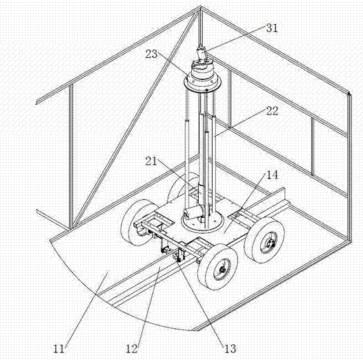
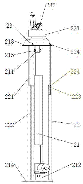
[0025] The bridge bottom surface crack detection device of the present invention mainly includes three modules: a traveling chassis, a camera orientation and attitude adjustment module, and a crack detection module. figure 1 It is a schematic diagram of the overall structure of a specific embodiment of the present invention, combined below figure 1 ~5 introduces it in detail.

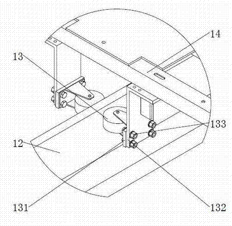
[0026] Such as figure 1 , 2 , the truss arm 11 of the bridge inspection vehicle extends below the bridge and is the motion platform of the entire crack inspection device. 12 is the lightweight guide rail installed on the truss arm 11, and the connection mode is a screw connection. The material of the lightweight guide rail can be wood or engineering plastics, and the length is the same as that of the truss arm 11 . 13 is the elastic guide wheel installed on the four-wheel chassis 14. There are two elastic guide wheels 13, which are symmetrically installed on both sides of the lightweight guide rail...


PUM


Abstract

The invention discloses a concrete bridge bottom crack detecting device, which is used for detecting cracks on a bridge bottom. A bridge detection vehicle is used as a work platform, and the device comprises a walking chassis, a camera direction and posture adjustment module and a crack detection module, wherein the walking chassis is arranged on a truss arm of the bridge detection vehicle, and can make linear reciprocating movement on the truss arm; the camera direction and posture adjustment module is arranged on the walking chassis and used for adjusting the direction and posture of the crack detection module; and the crack detection module is arranged on the camera direction and posture adjustment module and used for detecting cracks on the bridge bottom. By the adoption of the detecting device, quick detection of a bridge bottom crack image can be realized, and related data recorded by the system can be provided to engineers for evaluation on the crack damage conditions of a bridge and later analysis research.

Description

technical field [0001] The invention relates to the field of bridge detection, in particular to a bridge crack damage detection device. Background technique [0002] More than 90% of the damage of concrete bridges is caused by cracks. Engineering practice and theoretical analysis show that almost all concrete components work with cracks, but some cracks are so thin that they are even invisible to the naked eye (<0.05mm), generally there is no major harm to the normal use of the structure, and their existence is allowed; However, under the action of load or external physical and chemical factors, some cracks will continue to generate and expand new cracks, forming penetrating joints and deep joints. Cracks above 0.20-0.30mm will directly destroy the structural integrity, causing concrete carbonization, protection Layer spalling and steel bar corrosion form a mechanical discontinuity inside the bridge, which greatly reduces the bearing capacity of the bridge, and even coll...

Claims


Application Information

Patent Timeline
Patent Type & Authority Patents(China)
IPC IPC(8): G01B11/00G01B11/02H04N5/232F16M11/26F16M11/12
Inventor 尹周平宋俊余其竞童旭航凌云方阳吴纪昂田开望
Owner HUAZHONG UNIV OF SCI & TECH
Why Eureka
Try Eureka