Arrangement and method for detecting and/or locating a magnetic material in a region of action

一种磁性材料、作用区域的技术,应用在使用磁变量测量、使用核磁共振图像系统进行测量、应用等方向,能够解决长获取时间、求逆重建耗时、大量计算机内存等问题

Inactive Publication Date: 2011-11-16
KONINK PHILIPS ELECTRONICS NV
View PDF5 Cites 9 Cited by
  • Summary
  • Abstract
  • Description
  • Claims
  • Application Information

AI Technical Summary

Problems solved by technology

This calibration procedure requires very long acquisition times and also provides noise-contaminated system functions
Due to the large size of the system function matrix, solving the inverse reconstruction problem is also very time-consuming and requires a large amount of computer memory

Method used


Image

  • Arrangement and method for detecting and/or locating a magnetic material in a region of action
  • Arrangement and method for detecting and/or locating a magnetic material in a region of action
  • Arrangement and method for detecting and/or locating a magnetic material in a region of action

Examples


Embodiment Construction

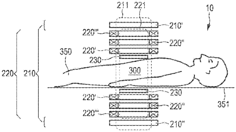
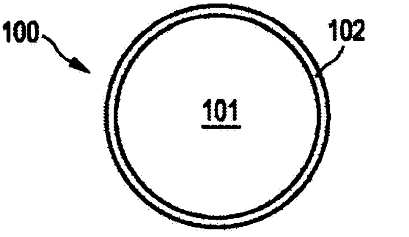
[0053] figure 1 Any object examined by means of the device 10 according to the invention is shown. figure 1 Reference numeral 350 in denotes an object, in this case a human or animal patient, arranged on a patient table, only the top part of which is shown. Before applying the method according to the invention, the magnetic particles 100 ( figure 1 not shown in ) is arranged in the active area 300 of the innovative device 10 . The magnetic particles 100 are placed in the active region 300 , for example by means of a liquid (not shown) containing the magnetic particles 100 which is injected into the body of the patient 350 , in particular prior to a therapeutic and / or diagnostic treatment, eg of a tumor.

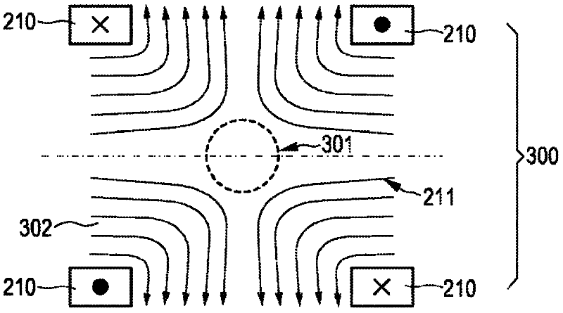
[0054] As an example of an embodiment of the present invention, figure 2 A device 10 is shown in , comprising a plurality of coils forming a selection means 210 whose extent defines an active area 300 also referred to as a treatment area 300 . For example, the selection ...


PUM


Abstract

In Magnetic Particle Imaging (MPI) the reconstruction requires the knowledge of a so called system function. This function describes the relation between spatial position and frequency response. For reasonable resolutions and field of views the system function becomes quite large, resulting in large acquisition times for the system function and high memory demand during reconstruction. The present invention proposes to reduce the size of the system function matrix by making use of structural properties of the matrix. Such properties are, for instance, spatial symmetries reducing the number ofcolumns and identical responses at different frequencies reducing the number of rows. In other embodiments the matrix can be transformed to a sparse representation using appropriate base functions.

Description

technical field [0001] The invention relates to a device for detecting and / or locating magnetic material in an active region. The invention also relates to a corresponding method and a computer program for controlling the device. Background technique [0002] Such a device is known from German patent application DE10151778A1. In the apparatus described in this publication, first, a magnetic field having a spatial distribution of magnetic field strength is generated such that a first subregion with a relatively low magnetic field strength and a second subregion with a relatively high magnetic field strength are formed in the examination region . The position in space of the sub-regions in the examination region is then shifted such that the magnetization of the particles in the examination region is changed locally. recording signals that depend on the magnetization in the examination zone, which has been influenced by a position shift in space of the sub-zones, and extrac...

Claims


Application Information

Patent Timeline
Patent Type & Authority Applications(China)
IPC IPC(8): A61B5/05G01R33/28G01R33/483
CPCA61B5/05A61B5/0515
Inventor J·E·拉米尔J·魏岑埃克B·格莱希
Owner KONINK PHILIPS ELECTRONICS NV
Why Eureka
Try Eureka