Structure that includes bolt fastening portion having higher resistance against external force

A structure and bolt technology, applied in the field of structures, can solve problems such as exceeding the friction retention capacity

Inactive Publication Date: 2011-11-16
TOYOTA JIDOSHA KK
View PDF6 Cites 0 Cited by
  • Summary
  • Abstract
  • Description
  • Claims
  • Application Information

AI Technical Summary

Problems solved by technology

However, in the event of a vehicle crash, unexpectedly large external forces are applied to the structure, exceeding its frictional holding capacity

Method used


Image

  • Structure that includes bolt fastening portion having higher resistance against external force
  • Structure that includes bolt fastening portion having higher resistance against external force
  • Structure that includes bolt fastening portion having higher resistance against external force

Examples


Embodiment Construction

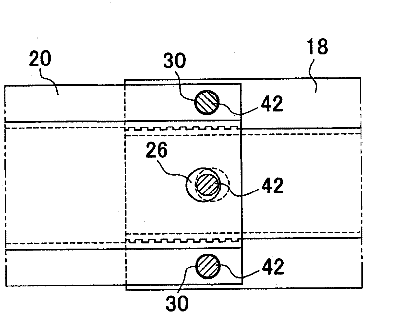
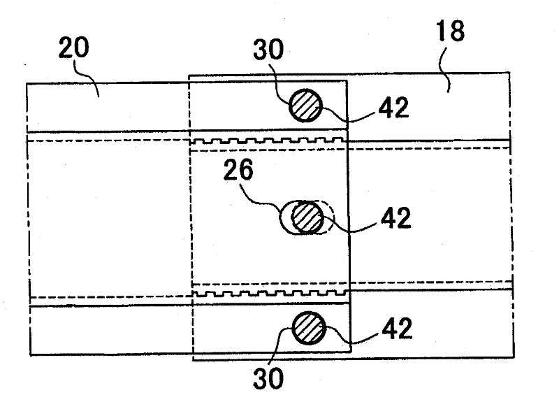
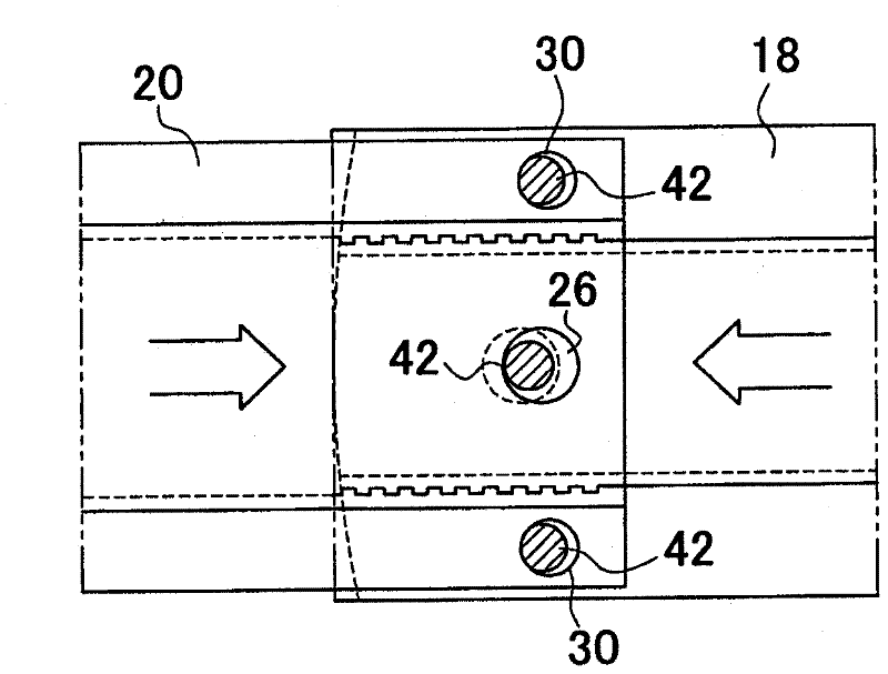
[0027] image 3 is a perspective view of an example of a floor cross member and a roof cross member of an automobile body attached at one end to a side frame of the vehicle body according to the present invention. Such as image 3 As shown, the vehicle body includes side frames 10 , a pair of center pillars 12 , floor rails 14 and roof rails 16 . Center pillars 12 are provided individually on the left and right sides of the vehicle. Each end of the floor cross member 14 is attached to the lower ends of the left and right center pillars 12 ( image 3 Only one of the center columns is shown). Also, each end of the roof cross member 16 is attached to the upper ends of the left and right center pillars 12, respectively.

[0028] The floor beam 14 includes a central portion 18 forming a central portion of the floor beam 14 and a gusset 20 attached to each end of the floor beam 14 . image 3 Only one of the gussets 20 attached to the ends of the floor beams 14 is shown. As in ...


PUM


Abstract

Disclosed is a structure (14) in which two structural members (18, 20) that each include thick portion and that have a plurality of bolt holes (26, 28, 30, 32), wherein the two structural members are overlapped at the thick portion and fastened together with bolts (42) at the plurality of bolt holes. In this structure, a certain amount of play is provided respectively for the bolts (42) at the bolt holes (26, 28, 30, 32) so that a shear force resulting from an external force applied to the structure (14) acting on the bolts (42) is even after at least one of the two structural members is deformed by the external force.

Description

technical field [0001] The present invention relates to a structure having a higher strength bolt fastening at which two structural members are screwed together. Background technique [0002] Japanese Patent No. 3936799 describes a beam structure for an automobile body or other body in which the beam spans between the side frames of the vehicle and the output side of the transmission is supported on the body. In this structure, each end of the beam is attached to the side frame with three bolts respectively passing through elongated bolt holes that are not aligned in line. In the event of a vehicle crash, the structure prevents the transmission and engine from protruding toward the floor, yet allows the transmission and engine to be displaced toward the rear. Furthermore, Japanese Patent Application Publication No. 2005-212503 (JP-A-2005-212503) describes an automobile body lower structure. In the structure, the floor cross member extends on the floor of the vehicle body i...

Claims


Application Information

Patent Timeline
Patent Type & Authority Applications(China)
IPC IPC(8): B62D25/08
CPCB62D25/04B62D25/06B62D21/15B62D27/065
Inventor 冈幸雄
Owner TOYOTA JIDOSHA KK
Why Eureka
Try Eureka