Detection method and system for MIMO system

A detection method and multi-output technology, applied in the field of communication, can solve the problem of complex node selection, and achieve the effect of reducing the number of node selections and simplifying node selection.

Active Publication Date: 2011-11-16
HONOR DEVICE CO LTD
View PDF2 Cites 9 Cited by
  • Summary
  • Abstract
  • Description
  • Claims
  • Application Information

AI Technical Summary

Problems solved by technology

[0004] During the research and practice of the prior art, the inventors of the present invention found that the existing QRM algorithm needs to retain more nodes, resulting in node selection is still very complicated

Method used


Image

  • Detection method and system for MIMO system
  • Detection method and system for MIMO system
  • Detection method and system for MIMO system

Examples


Embodiment 1

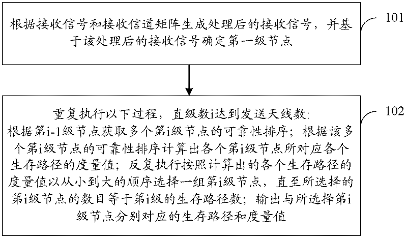
[0033] A detection method for a multiple-input multiple-output system, comprising: generating a processed received signal according to a received signal and a received channel matrix, and determining a first-level node based on the processed received signal, and repeating the following process until the number i When the number of transmitting antennas is reached, i is a positive integer greater than 1:

[0034] Obtain the reliability ranking of at least two i-th level nodes according to the i-1th level nodes; calculate the metric value of each survival path corresponding to each i-th level node according to the reliability ranking of at least two i-th level nodes;

[0035] Repeatedly select a group of i-th level nodes in ascending order according to the metric value of each survival path, until the number of selected i-th level nodes is equal to the number of survival paths of the i-th level;

[0036] Outputting survival paths and metric values ​​for decoding sent signals cor...

Embodiment 2

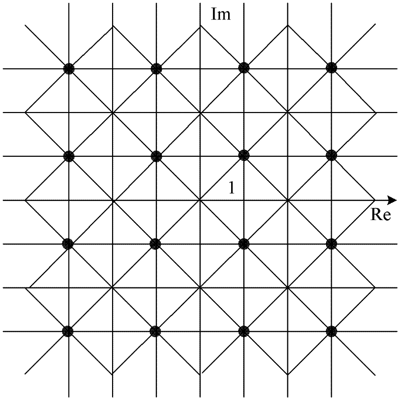
[0084] Such as image 3 As shown, in this embodiment, the preset two-dimensional space is a two-dimensional space with constellation points of 16QAM, and the two-dimensional space is divided into 128 areas, and each area is called a block, corresponding to each block, is One reliability ranking table is stored, that is, in this embodiment, 128 reliability ranking tables are stored. Each reliability ranking table correspondingly records the corresponding constellation point ranking when the node is located in the area. That is to say, as long as it is determined which block the node is located in, the constellation point ranking can be obtained by looking up the reliability ranking table of the block, thereby obtaining the reliability ranking of the node.

[0085] An example will be given below to describe in detail.

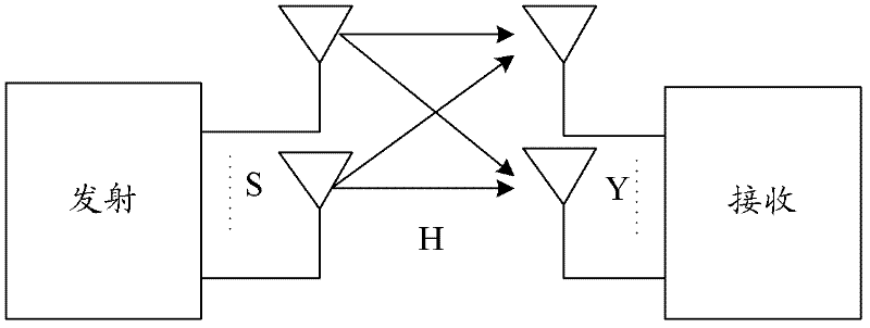
[0086] Scenario: see Figure 1a , in this MIMO system, there are T transmitting antennas at the transmitting end, and R receiving antennas at the receiving end...

Embodiment 3

[0123] In the second embodiment, the constellation point rankings of all regions are stored. The difference from the second embodiment is that in this embodiment, only the constellation point rankings of some regions are stored.

[0124] For example, it can be as follows:

[0125] Such as Figure 1c As shown, due to the symmetry of the constellation point coordinates, only the constellation point ordering of some areas can be stored. If the estimated value of the node is not in the area where the reliability ordering is stored, the estimated value of the node can be mapped to the area where the reliability ordering is stored. In the area, and look up the table to get the constellation point sorting, and then reverse the obtained sorting to get the corresponding sorting of the block where the original node estimated value is located.

[0126] The following uses an example of storing only reliability sorting tables corresponding to blocks in the first quadrant area for illustra...


PUM


Abstract

A detection method for an MIMO (Multiple-Input Multiple-Output) system comprises the steps of: generating a processed receiving signal based on a receiving signal and a receiving channel matrix, and determining a first-stage node based on the processed receiving signal; executing the following process repeatedly until a stage number i reaches the number of trasmitting antennas, wherein the i is apositive integer greater than 1: obtaining a reliability ordering of at least two i-stage nodes based on an i-1-stage node; calculating a measuring value of each surviving route corresponding to the each i-stage node based on the reliability ordering of the at least two i-stage nodes; repeatedly executing the step of selecting a set of the i-stage nodes in order from small to large according to the measuring value of the each surviving route until number of the selected i-stage nodes is equal to the number of the surviving route of the i-stage; and outputting the surviving route and the measuring value which are respectively corresponding to the selected i-stage nodes and used for coding a sending signal. A detection system comprises a first processing module and a second processing model.

Description

technical field [0001] The invention relates to the field of communication technology, in particular to a detection method and system for a multiple-input multiple-output system. Background technique [0002] In a Multiple-Input Multiple-Output (MIMO, Multiple-Input Multiple-Output) system, the model of the received signal can be expressed as: Y=HS+N, where Y represents the received signal, S is the signal sent by the transmitting antenna, and H is the channel response , N is the noise. For example, see Figure 1a , in this MIMO system, there are T transmitting antennas at the transmitting end, and R receiving antennas at the receiving end, then the transmitted signal sequence of T transmitting antennas can be expressed as S=[s 1 ,s 2 ,...s T ] T , the signal vectors of the corresponding R×1 receiving antennas can be expressed as Y=[y 1 ,y 2 ,...y R ] T , with zero mean over the receiving antennas and variance σ 2 The white Gaussian noise can be expressed as N=[n 1...

Claims


Application Information

Patent Timeline
Patent Type & Authority Applications(China)
IPC IPC(8): H04L1/06H04B7/08
CPCH04B7/08H04L25/03891H04B7/0413H04L1/06
Inventor 李景玉高振兴刘华斌江长国
Owner HONOR DEVICE CO LTD
Why Eureka
Try Eureka