Sliding limit seat

A seat and limit technology, which is applied to chairs, other seat furniture, stools, etc., can solve the problems of inability to meet ergonomic requirements, incomplete limit, large limit intervals, etc., and achieve system rigidity enhancement and easy operation Convenience, the effect of increasing the limit density

Inactive Publication Date: 2011-11-23
GREATWALL INFORMATION IND +1
View PDF5 Cites 6 Cited by
  • Summary
  • Abstract
  • Description
  • Claims
  • Application Information

AI Technical Summary

Problems solved by technology

Its limit mechanism widely adopts limit methods such as pins and marbles, which often have shortcomings such as incomplete limit, troublesome oper

Method used


Image

  • Sliding limit seat
  • Sliding limit seat
  • Sliding limit seat

Examples


Example Embodiment

[0023] Example 1:

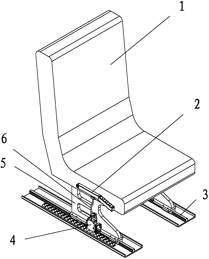
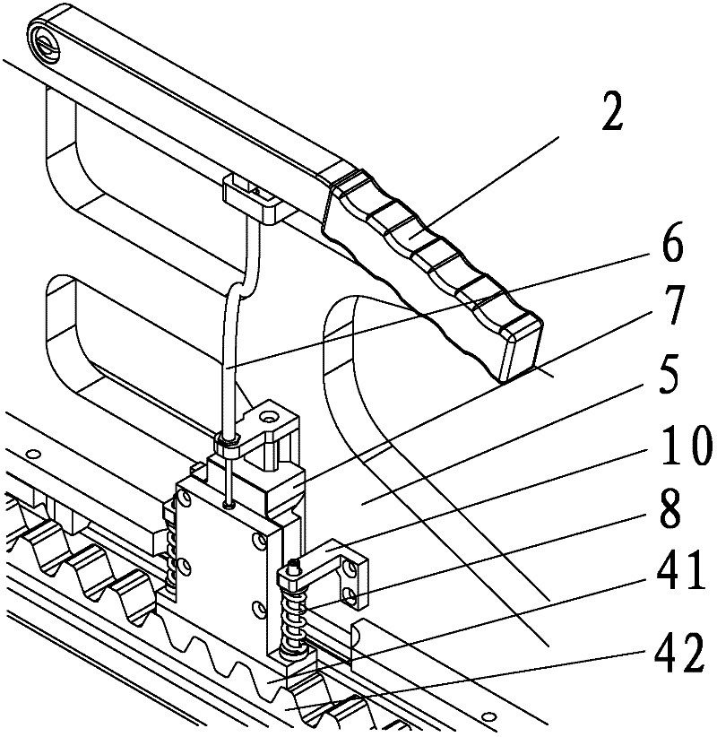
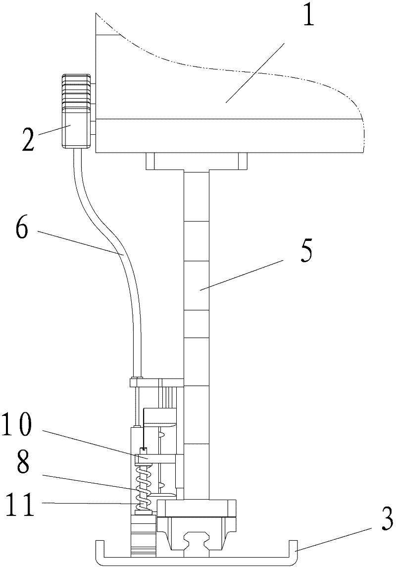
[0024] like Figure 1-4 As shown, a sliding limit seat is characterized in that it includes linear guide rails, meshing racks, brake lines, handles, seat pans, brackets, compression springs and the like.

[0025] The seat pan is fixed on the bracket, and the bottom of the bracket is set on two linear guide rails and can slide forward and backward along the linear guide rails in the unlocked state; the rack pair is composed of a fixed lower rack and a movable upper rack, and the lower rack is opposite to each other. The upper rack is fixed on the slider; the vertical guide rail is fixed on the bracket, the locking mechanism composed of the upper rack and the slider is set on the vertical guide rail, the lower end of the brake line is connected with the locking mechanism, and the brake line The upper end of the handle is connected to the handle, and the rotation fulcrum of the handle is set on the bracket or the seat pan. On the bracket, there is a protrudin...


PUM


Abstract

The invention discloses a sliding limit seat which comprises a seat pan, a bracket supporting the seat pan, a handle, a braking line, two linear guide rails, a rack pair, a pressure spring and a vertical guide rail, wherein the seat pan is fixed on the bracket, wherein the seat pan is fixed on the bracket; the bracket bottom is arranged on the two linear guide rails and can slide back and forth along the linear guide rails in an unlocked state; the rack pair consists of a fixed rack and a movable locking mechanism; the rack is static relative to the linear guide rails; the vertical guide rail is fixed on the bracket; the locking mechanism is arranged on the vertical guide rail; the lower end of the braking line is connected with the locking mechanism; the upper end of the braking line is connected with the handle; a rotation fulcrum of the handle is arranged on the bracket or seat pan; an extension component for mounting the pressure spring is arranged on the bracket; and the pressure spring for reset is arranged between the locking mechanism and the extension component along the vertical direction. The sliding limit seat is simple to operate and can realize reliable limit of intensive points.

Description

technical field [0001] The invention relates to a sliding limit seat. Background technique [0002] Sliding limit seats are widely used in military industry, transportation, entertainment, medical and other industries. Its limit mechanism widely adopts limit methods such as bolts and marbles, which often have shortcomings such as incomplete limit, troublesome operation, low reliability, and large limit intervals. Many defects have gradually failed to meet today's increasingly demanding ergonomic requirements. Contents of the invention [0003] The technical problem to be solved by the present invention is to propose a sliding limit seat, which is easy to operate and can realize highly reliable limit of dense points. [0004] Technical solution of the present invention is as follows: [0005] A sliding limit seat, including a seat pan, a bracket supporting the seat pan, a handle, a brake line, two linear guide rails, a rack pair, a slider, a compression spring and a vert...

Claims


Application Information

Patent Timeline
IPC IPC(8): A47C1/00A47C7/00
Inventor 罗成李明舒碧湘程天张荣郭兴
Owner GREATWALL INFORMATION IND
Why Eureka
Try Eureka