
Main jib structure for fork installing machine

A technology for forklifts and main arms, applied in the direction of lifting devices, etc., can solve the problems of poor uniformity of force on the boom, difficult to release welding stress, and short use time of the main arm, so as to improve the stability and lifting performance, Reduce welding stress and welding process difficulty, light weight effect

Active Publication Date: 2011-11-23
XUZHOU XUGONG SPECIAL CONSTR MASCH CO LTD
View PDF7 Cites 3 Cited by
  • Summary
  • Abstract
  • Description
  • Claims
  • Application Information

AI Technical Summary

Problems solved by technology

At present, the main arm structure of the forklift machine generally adopts four pieces of plate tailor-welded to form a standard quadrilateral structure. Due to the unreasonable design structure, there are many butt welds, and the welding stress is not easy to release. The force uniformity is not good, resulting in adverse effects such as short service life and cracking of the main arm

Method used


Image

  • Main jib structure for fork installing machine
  • Main jib structure for fork installing machine
  • Main jib structure for fork installing machine

Examples


Embodiment 1

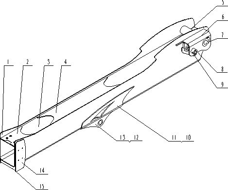
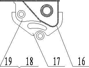
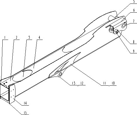
[0010] Embodiment 1: The main arm includes: U-shaped main arm plate 1, front upper web 2, upper cover plate 3, upper web 4, main shaft sleeve 5, bending cover plate 6, crescent plate 7, first shaft sleeve 8. The second shaft sleeve 9, the left web 10, the right web 11, the oil cylinder support plate 12, the third shaft sleeve 13, the front side plate 14, the front lower rib plate 15, the rear inner curved plate 16, the rear side Web 17, rear inner web 18 and fourth bushing 19. The U-shaped main arm plate 1 is the main body, and the upper cover plate 3 is welded on the inner side of the U-shaped main arm plate 1 to form a high-strength box structure; the front upper web 2 and the upper web 4 are respectively welded on the front of the upper cover plate 3 and the middle position; the second bushing 9 is respectively welded on the two sides behind the wall plate of the U-shaped main arm plate 1; the bending cover plate 6 is welded on the rear side of the wall plate of the U-shape...


PUM


Abstract

The invention discloses a main jib structure for a fork installing machine and belongs to main jib structures of engineering machinery. The upper cover plate of a main jib is welded at the inner side of a U-shaped main jib plate to form a high-strength box structure; second shaft sleeves are respectively welded on the two sides of the rear surface of the wallboard of the U-shaped main jib plate; a bend cover plate is welded on one side of the rear surface of the wallboard of the U-shaped main jib plate; a crescent plate is welded on the rear surface of a main shaft sleeve at the upper face ofthe wallboard of the U-shaped main jib plate; a rear web plate, a rear inner web plate and a forth shaft sleeve are respectively welded on one side of the rear surface of the wallboard of the U-shaped main jib plate; cylinder support plates are symmetrically welded on a left web plate and a right web plate; third shaft sleeves are welded on the left web plate and the right web plate; and a front lower rib plate is welded in the middle of a front plate at the lower part of the front end of the U-shaped main jib plate. The main jib structure of the fork installing machine has the advantages that the U-shaped main jib plate and the upper cover plate are combined to greatly reduce welding lines; each web plate is in a curved shape combined with jib rest stress distribution, thus effectively ensuring the stress of the main jib structure to be more uniform and improving the integral strength; and the bearing capability is strong, the structure is concise and the weight is light.

Description

technical field [0001] The invention relates to a main arm structure of construction machinery, in particular to a forklift main arm structure. Background technique [0002] The forklift is a multi-purpose lifting and handling equipment, which combines stability and high work efficiency, and is suitable for a variety of material handling environments. The forklift has its unique structure. The front end is the working device. The working device includes the main arm, the telescopic boom (included in the main arm) and the floating fork. In the lifting operation, the main boom is mainly used to bear the gravity generated by the entire telescopic boom, forks and loads. At present, the main arm structure of the forklift machine generally adopts four pieces of plate tailor-welded to form a standard quadrilateral structure. Due to the unreasonable design structure, there are many butt welds, and the welding stress is not easy to release. The force uniformity is not good, resulti...

Claims


Application Information

Patent Timeline
IPC IPC(8): B66F9/075
Inventor 高晔商飞宋红兵曹磊贾吉鹏石锋华
Owner XUZHOU XUGONG SPECIAL CONSTR MASCH CO LTD
Learn More