Optical film

An optical film and light-collecting technology, applied in diffusing elements, prisms, etc., can solve the problems of light energy dispersion and light energy reduction, reduce the probability of total reflection, improve light uniformity, and improve light utilization efficiency Effect

Inactive Publication Date: 2013-09-25
AU OPTRONICS CORP
View PDF9 Cites 0 Cited by
  • Summary
  • Abstract
  • Description
  • Claims
  • Application Information

AI Technical Summary

Problems solved by technology

However, because the diffusion layer 220 tends to disperse part of the light energy too much, the available light energy of the prism column 230 becomes less.

Method used


Image

  • Optical film
  • Optical film
  • Optical film

Examples


Embodiment Construction

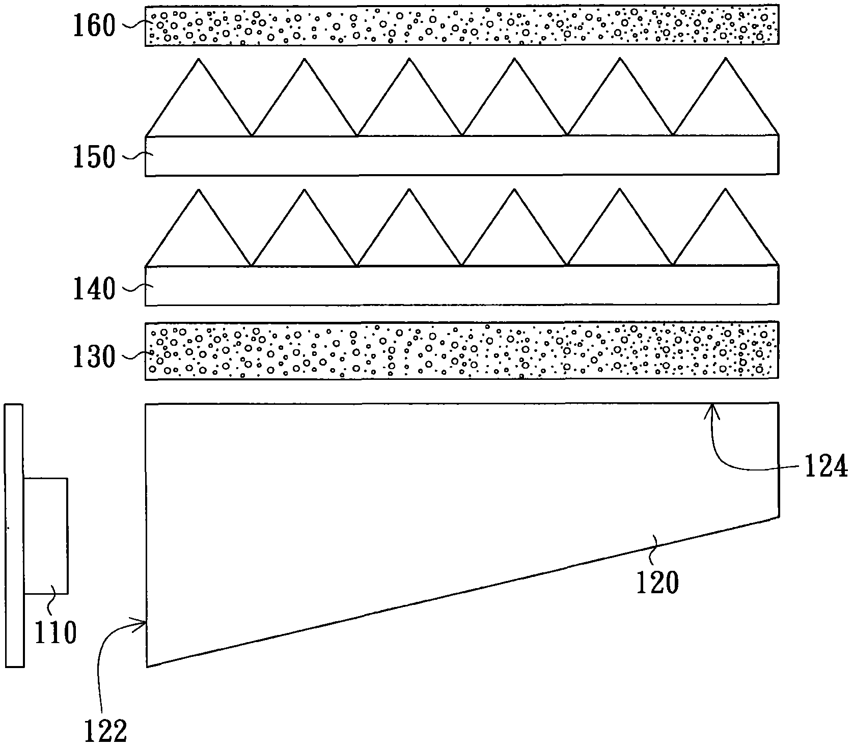
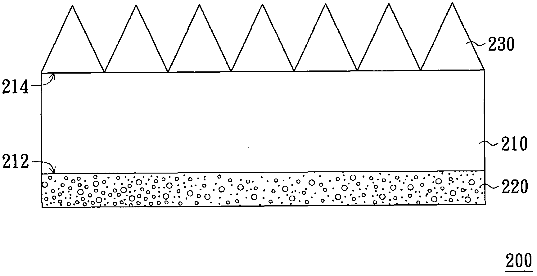
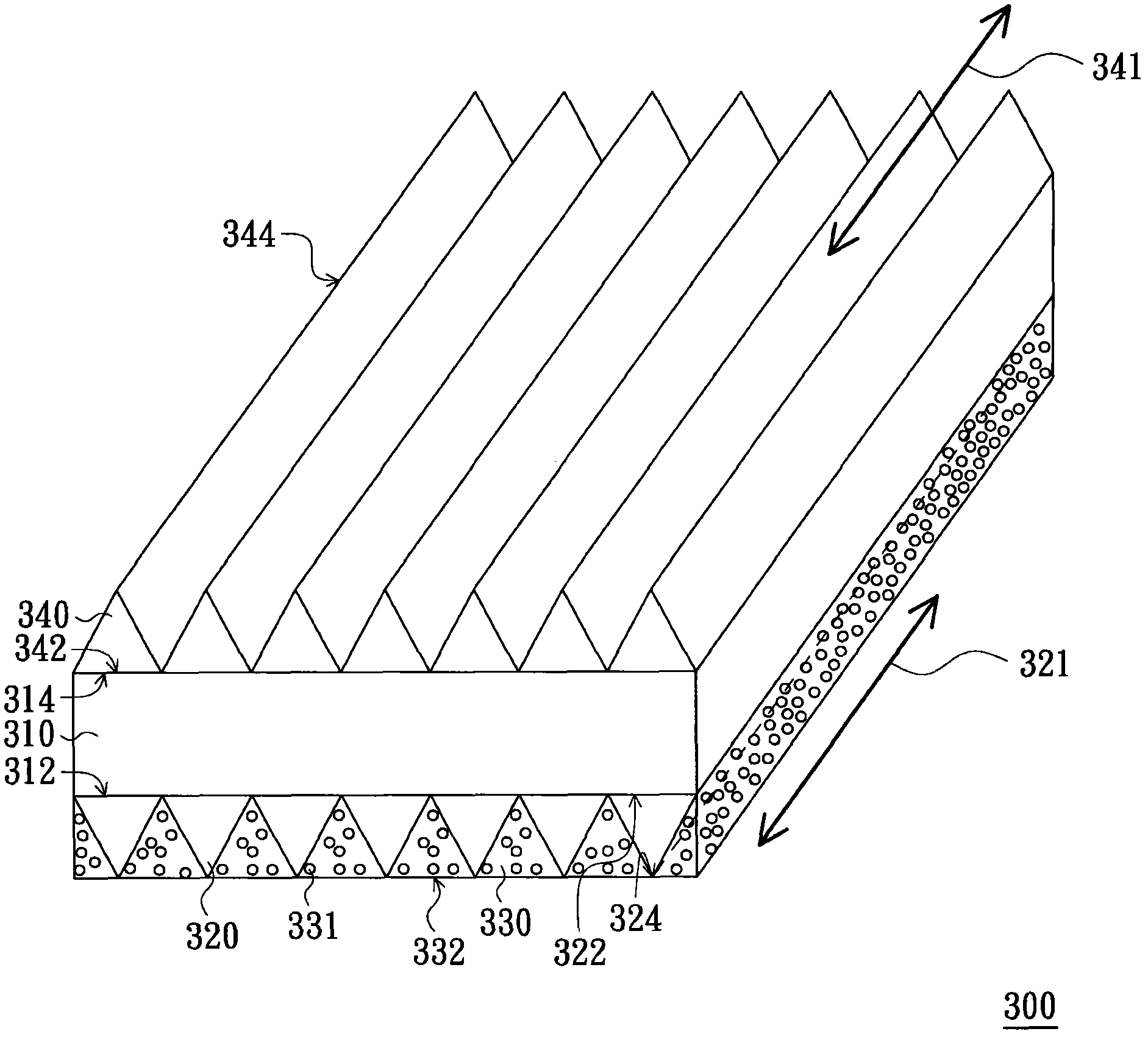
[0058] image 3 It is a three-dimensional schematic diagram of an optical film according to an embodiment of the present invention. Please refer to image 3 , the optical film 300 of this embodiment includes a substrate 310 , a plurality of first light-collecting structures 320 and a plurality of diffusion structures 330 . The substrate 310 has a light incident surface 312 and a light exit surface 314 opposite to each other, and the distance between the light incident surface 312 and the light exit surface 314 is, for example, between 30 microns and 300 microns.

[0059]The diffusion structures 330 are disposed on the light incident surface 312 , and there are gaps between two adjacent diffusion structures 330 , and the first light collection structures 320 are respectively disposed in these gaps, and the first light collection structures 320 are adjacent to the diffusion structures 330 . From another perspective, each first light collecting structure 320 has a bottom surfac...


PUM


Abstract

The invention provides an optical film, including a substrate, a plurality of first light gathering structures and a plurality of diffusion structures. The substrate has a light inlet face and a light outlet face which are opposite. The first light gathering structures are disposed on the light inlet face. Each of first light gathering structures has opposite bottom face and top corner and the bottom face is connected with the ligth inlet face. The diffusion structures are respectively disposed in the gaps between the first light gathering structures. The diffusion structures are adjacent to the first light gathering structures and the top corner of each of the first light gathering structures and the bottom face far away from the substrate of each of the diffusion structures are in the same plane. The optical film has the good light gathering efficiency.

Description

technical field [0001] The invention relates to an optical film, and in particular to an optical film for homogenizing a surface light source. Background technique [0002] The liquid crystal display includes a liquid crystal display panel and a backlight module. Since the liquid crystal display panel itself does not emit light, the display light source required by the liquid crystal display panel needs to be provided by the backlight module. [0003] figure 1 It is a schematic cross-sectional view of a known backlight module. Please refer to figure 1 , the known backlight module 100 includes a light source 110 and a light guide plate 120, wherein the light source 110 is arranged next to the light incident surface 122 of the light guide plate 120 to provide light to the light guide plate 120, and the light guide plate 120 is used to convert the light into light from the light output surface 124 The outgoing surface light source. In addition, in order to improve the unifo...

Claims


Application Information

Patent Timeline
Patent Type & Authority Patents(China)
IPC IPC(8): G02B5/04G02B5/02
Inventor 蔡怡均陈志光谌思廷许文铭黄任伟庄淑婷蔡政旻赖明昇
Owner AU OPTRONICS CORP
Why Eureka
Try Eureka