

Finite element modeling and bearing method for line-tower coupling system of power transmission tower
A transmission tower, finite element technology, applied in the direction of electrical digital data processing, special data processing applications, instruments, etc., can solve problems such as missing data, spending a lot of time and energy, and affecting the accuracy and precision of finite element analysis
- Summary
- Abstract
- Description
- Claims
- Application Information
AI Technical Summary
Problems solved by technology
Method used
Image

Examples
example 1
[0036] Example 1: Finite element analysis of 110kvZGU linear tower line tower coupling system
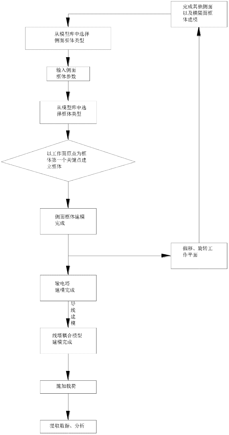
[0037] 1. Establish the finite element model of the overall structure of the transmission tower. When entering the main interface of software operation, the user selects the type of frame from the model library and enters the model parameters. The user can input the relevant parameters of the model according to the example. After entering the relevant parameters and determining the finite element model of a single frame, follow the transmission tower For the actual shape of the overall structure, by changing the working plane, continue to follow the above steps to determine the finite element model of the next frame. This model applies the DZHG-1 diaphragm, fork-shaped diaphragm, rhombus-shaped diaphragm, tower legs with three equal fork-shaped outriggers, fork-shaped triangular supplementary boom tower body, fork-shaped tower body, and fork-shaped tower body. Side structure forms ...
example 2
[0041] Example 2: Finite element analysis of 220kv SJT corner tension tower line-tower coupling system
[0042] 1. Establish the finite element model of the overall structure of the transmission tower. When entering the main interface of software operation, the user selects the type of frame from the model library and enters the model parameters. The user can input the relevant parameters of the model according to the example. After entering the relevant parameters and determining the finite element model of a single frame, follow the transmission tower For the actual shape of the overall structure, by changing the working plane, continue to follow the above steps to determine the finite element model of the next frame. This model applies the DZHG-1 diaphragm, fork-shaped diaphragm, diamond-shaped diaphragm, cross diaphragm and other diaphragm forms, as well as the simplified diagram of the 332-type triangular supplementary material connecting legs, the fork-shaped triangular ...
example 3
[0046] Example 3: Finite element analysis of 500kv SJTZB42A wine glass single loop linear tower line tower coupling system
[0047] 1. Establish the finite element model of the overall structure of the transmission tower. When entering the main interface of software operation, the user selects the type of frame from the model library and enters the model parameters. The user can input the relevant parameters of the model according to the example. After entering the relevant parameters and determining the finite element model of a single frame, follow the transmission tower For the actual shape of the overall structure, by changing the working plane, continue to follow the above steps to determine the finite element model of the next frame. This model applies the DZHG-1 diaphragm, fork-shaped diaphragm, diamond-shaped diaphragm, cross diaphragm and other diaphragm forms, as well as the simplified diagram of the 332-type triangular supplementary material connecting legs, the for...
PUM
 Abstract
Description
Claims
Application Information