Electric drive apparatus
一种电传动、电动机的技术,应用在机电装置、电动组件、电气元件等方向,能够解决增加电导体阻抗、降低电容器性能、控制单元尺寸大等问题
- Summary
- Abstract
- Description
- Claims
- Application Information
AI Technical Summary
Problems solved by technology
Method used
Image
Examples
no. 1 example
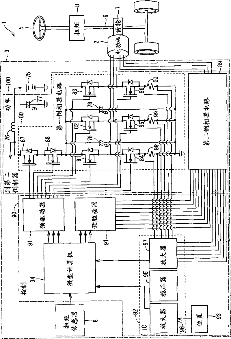
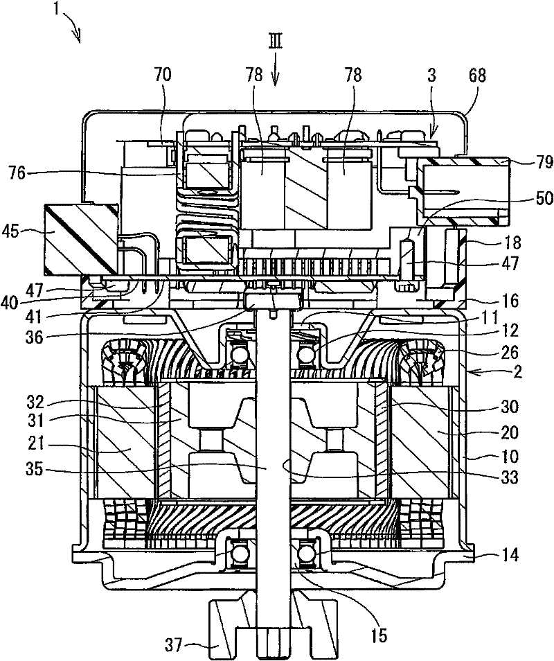
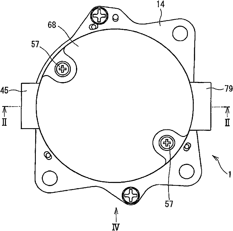
[0051] A transmission according to a first embodiment of the invention is shown in Figure 1 to Figure 17 and indicated by the number 1. The transmission 1 is applied to an electric power steering system (referred to as EPS) of a vehicle.
[0052] First refer to figure 1 Describe the electrical configuration of the EPS. The electrical configurations described hereinafter can be applied to other embodiments. Such as figure 1As shown in , the electric transmission 1 is used to drive the column 6 through a gear 7 attached to the column 6 (rotation shaft of the steering wheel 5 ) to generate rotational torque to assist the steering operation of the steering wheel 5 of the vehicle. Specifically, when the driver operates the steering wheel 5, the electric transmission 1 assists the driver in the steering operation of the steering wheel 5 by detecting the steering torque generated in the column shaft 6 and acquiring vehicle speed information from CAN (Control Area Network), not s...
no. 2 example
[0104] Figures 21 to 29 shows an electric transmission according to a second embodiment of the invention. According to the second embodiment, the heat sink 250 has two heat radiation blocks 251 . Two module units 260 and 270 are provided for each of the heat radiation blocks 251 . That is, four module units 260 and 270 are installed on the heat sink 250 .
[0105]One module unit 260 is arranged on the top outer wall of the heat radiation block 251 on the side of the power circuit substrate 70 . Another module unit 270 is arranged on the side outer wall of the heat radiation block 251 . That is, the semiconductor module unit 260 is arranged generally perpendicular to the rotation center of the shaft 35 , and the semiconductor module unit 270 is arranged generally parallel to the rotation center of the shaft 35 .
[0106] The semiconductor module units 260 and 270 have four semiconductor modules 261 to 264 and 271 to 274 and metal substrates 265 and 275 , respectively. The...
no. 3 example
[0119] Figure 30 to Figure 33 shows an electric transmission according to a third embodiment of the invention. This embodiment is a modification of the first embodiment.
[0120] According to the third embodiment, the first smoothing capacitor 77, the second smoothing capacitor 78, and the choke coil 76 are arranged differently from the first embodiment. These large-sized electronic parts are arranged such that the first smoothing capacitor 77 , the choke coil 76 and the second smoothing capacitor 78 are arranged in this order on the power circuit substrate 70 from the power circuit connector 79 side. The second smoothing capacitor 78 is arranged such that an imaginary line Z connecting the axes of the second smoothing capacitor 78 forms a square shape when viewed in the axial direction from one axial side of the shaft 35 .
[0121] Figure 31 to Figure 33 The conductors formed in the power circuit substrate 70 are shown in . Figure 31 The conductor patterns of the fourt...
PUM
 Abstract
Description
Claims
Application Information
 - R&D
- Intellectual Property
- Life Sciences
- Materials
- Tech Scout
- Unparalleled Data Quality
- Higher Quality Content
- 60% Fewer Hallucinations
Browse by: Latest US Patents, China's latest patents, Technical Efficacy Thesaurus, Application Domain, Technology Topic, Popular Technical Reports.
© 2025 PatSnap. All rights reserved.Legal|Privacy policy|Modern Slavery Act Transparency Statement|Sitemap|About US| Contact US: help@patsnap.com


