Hot tip vein therapy device

A vein, steam generation technology, applied in the direction of treatment, electrotherapy, heating surgical instruments, etc., can solve the problems of inconsistent results, not used in the treatment of distorted surface varicose veins spider-like vascular disease, time-consuming, etc.

Inactive Publication Date: 2011-11-23
VENITI
View PDF6 Cites 1 Cited by
  • Summary
  • Abstract
  • Description
  • Claims
  • Application Information

AI Technical Summary

Problems solved by technology

This is time consuming and can lead to inconsistent results
Additionally, due to the size and / or stiffness of the catheter shaft and laser fiber, none of these treatments are currently available for the treatment of distorted superficial varices or larger spider veins

Method used


Image

  • Hot tip vein therapy device
  • Hot tip vein therapy device
  • Hot tip vein therapy device

Examples


Embodiment Construction

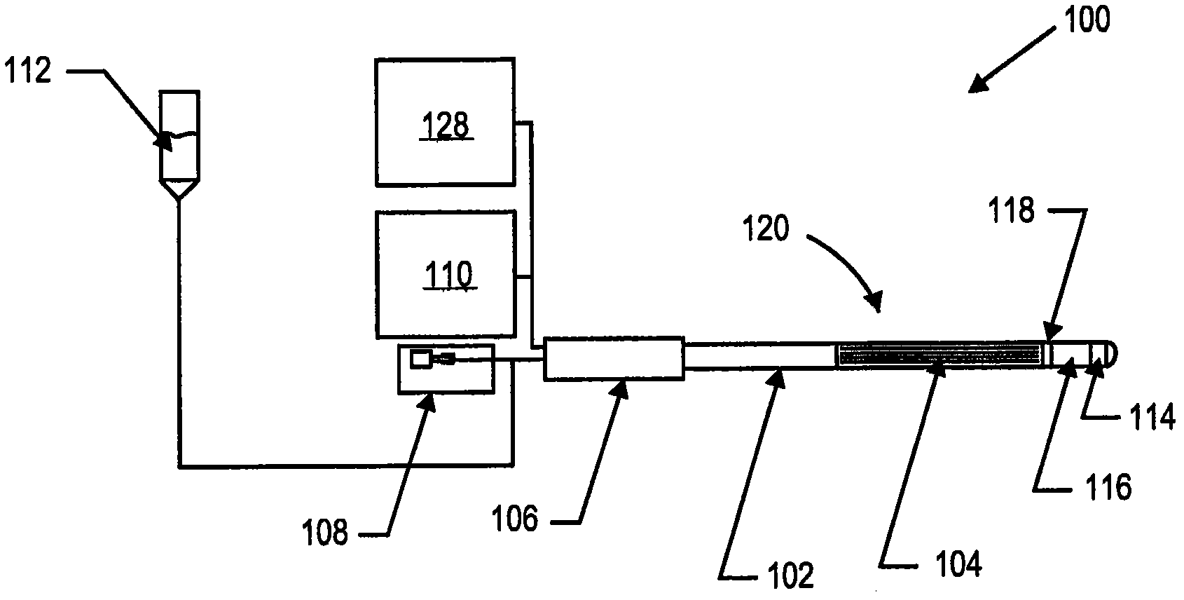
[0043]One embodiment of the present invention provides a catheter-based vapor therapy system that generates vapor at a distal end. The distal tip of the catheter is small enough to fit not only within the GSV, but also the smaller blood vessels within the patient's leg. The vapor therapy system may be used to treat varicose veins or for reduction therapy. Vapor generating catheters according to this embodiment can be made with diameters in the range of 4 Fr to 10 Fr, which can be used to treat a common range of veins and / or vessels, including GSVs and main branches emanating therefrom, since the diameter of the catheter is easily adapted in these blood vessels. However, in other embodiments, the catheter may be greater than 10 Fr or less than 4 Fr.

[0044] One aspect of the vapor therapy system according to this embodiment is the heat source at the distal end of the catheter that causes the vapor phase change of the liquid, particularly the size and efficiency of the heat s...


PUM


Abstract

Methods and apparatus for generating vapor within a catheter are provided which may include any number of features. One feature is generating vapor with an electrode array within a catheter. Another feature is sensing an impedance of the electrode array, and adjusting the power delivered to the electrode array to fully generate vapor within the catheter. Another feature is delivering the vapor to a vein of a patient for vein reduction therapy.

Description

[0001] CROSS-REFERENCE TO RELATED APPLICATIONS [0002] This application is pursuant to 35 U.S.C. 119 requirements of U.S. Provisional Patent Application Nos. 61 / 115,864, filed November 18, 2008, entitled "Thermal Tip Vein Treatment Device" and filed July 24, 2009, entitled "Thermal Priority to U.S. Provisional Patent Application No. 61 / 228,298, "Apex Vein Treatment Device." These provisional applications are hereby incorporated by reference in their entirety. [0003] References [0004] All publications and patent applications mentioned in this specification are herein incorporated by reference as if each individual publication or patent application were specifically and individually indicated to be incorporated by reference herein. Background of the Invention [0005] The venous system of the human lower extremity basically consists of a superficial venous system, a deep venous system, and a perforating vein connecting the two systems. The superficial system includes the...

Claims


Application Information

Patent Timeline
Patent Type & Authority Applications(China)
IPC IPC(8): A61B18/12A61M25/00A61B17/22A61N1/00
CPCA61B18/04A61B17/00008A61B2018/00017A61B2018/048
Inventor J·杰克森S·H·特里伯蒂奇G·M·格拉泽郑惇之J·M·塔塔格利亚F·M·桑德
Owner VENITI
Why Eureka
Try Eureka