Water-sealed ring cooler

Active Publication Date: 2011-11-30
HUATIAN NANJING ENG & TECH CORP MCC
View PDF6 Cites 22 Cited by
  • Summary
  • Abstract
  • Description
  • Claims
  • Application Information

AI Technical Summary

Problems solved by technology

Such a large amount of air leakage will not only affect the cooling effect of the ring cooler, consume a lot of energy, but also cause a lot of dust on the work site and serious environmental pollution
[0003] In addition, although the sealing performance of the existing domestic annular coolers has been greatly improved, their weight is about 40% larger than that of traditional annular coolers, and the structure is complex, inconvenient to use and maintain, and the cost is also high. There are inherent shortcomings in both, and it is difficult to popularize and use

Method used


Image

  • Water-sealed ring cooler
  • Water-sealed ring cooler
  • Water-sealed ring cooler

Examples


Embodiment Construction

[0037] The present invention will be further described below in conjunction with the accompanying drawings.

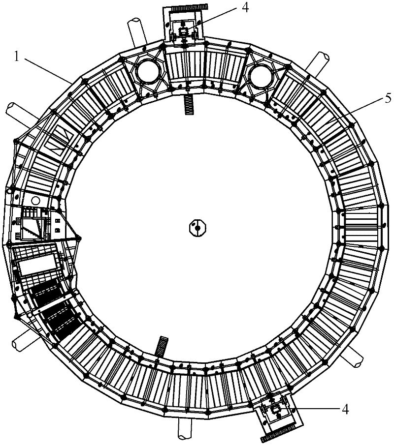
[0038] As shown in the figure, the water-sealed annular cooler of the present invention includes:

[0039] body 1;

[0040] A slewing system, arranged on the machine body 1, includes a rotary power drive device 4 and a rotary frame 5 that rotates under the drive of the rotary power drive device 4;

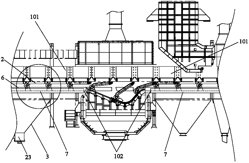
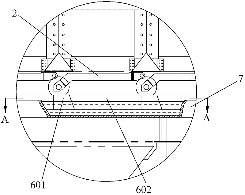
[0041] The trolley 2 is set on the revolving frame 5;

[0042] The air blowing system is placed under the revolving frame 5, including a blower 23 and a bellows 3 arranged between the air outlet of the blower 23 and the revolving frame; and,

[0043] The water sealing device is composed of two sets of water seals with the same structure, which are respectively arranged on the outer ring side and the inner ring side of the trolley 2 and / or the rotary frame 5 rotating circular track (such as Figure 6 shown), and between the bellows 3 and the trolley 2 and / or the revolving...


PUM


Abstract

The invention discloses a water-sealed circular cooler which mainly aims at solving the problem of poor sealing effect of the existing circular cooler. The water-sealed circular cooler comprises a cooler body, a rotation system, a trolley, a blower system and water-sealed device, wherein the rotation system is arranged on the cooler body, and comprises a rotation power drive device and a rotationframework driven to rotate by the rotation power drive device; the trolley is arranged on the rotation framework; the blower system is arranged below the rotation framework, and comprises a blower and an air box arranged between the air outlet of the blower and the rotation framework; the water-sealed device is composed of two sets of water-sealed parts having the same structure, and the two setsof water-sealed parts are respectively arranged at the outer ring side and the inner ring side of the annular rotation track of the trolley and/or rotation framework and are positioned between the air box and the trolley and/or rotation framework; each water-sealed part comprises a water tank and a sealing plate; and the water tank is fixed on the cooler body, one end of the sealing plate is inserted in the water tank, and the other end is fixed below the trolley and/or the rotation framework.

Description

technical field [0001] The invention relates to the field of metallurgical equipment, in particular to an annular cooler with water as a sealing medium. Background technique [0002] The sealing device of the traditional annular cooler mostly adopts the structure of dynamic and static rubber 221 and 222, and its typical form is as follows Figure 14 shown. In the actual engineering application process, the inventors found that: due to the existence of certain errors in the manufacturing and installation process of the annular cooler, such errors will easily cause the rubber strip to be caught by the moving platform after it is put into production and operation. The car was torn, resulting in increased air leakage from the ring cooler. According to calculations, the air leakage rate of traditional annular coolers is generally between 30% and 40%. Such a large amount of air leakage will not only affect the cooling effect of the ring cooler and consume a lot of energy, but al...

Claims


Application Information

Patent Timeline
Patent Type & Authority Applications(China)
IPC IPC(8): F27D15/02
Inventor 黄河叶学农
Owner HUATIAN NANJING ENG & TECH CORP MCC
Why Eureka
Try Eureka