electric motor

A technology of electric motors and sub-motors, applied in the field of electric motors, can solve problems such as inefficiency, and achieve the effect of reducing the demand for capacitors

Inactive Publication Date: 2011-11-30
PROTEAN ELECTRIC LIMITED
View PDF5 Cites 9 Cited by
  • Summary
  • Abstract
  • Description
  • Claims
  • Application Information

AI Technical Summary

Problems solved by technology

However, for an electric motor expected to operate over a wide speed / torque range, such as one designed to propel a vehicle, the motor will inevitably need to operate in a relatively inefficient speed / torque range at all times

Method used


Image

  • electric motor
  • electric motor
  • electric motor

Examples


Embodiment Construction

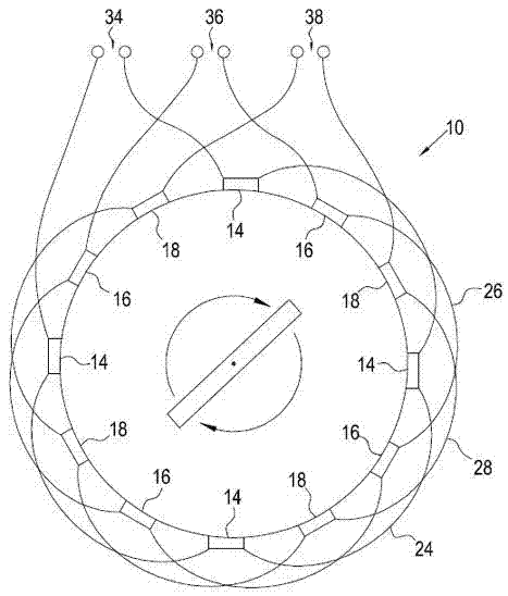
[0035] The described embodiment of the invention is an electric motor for a wheel. The electric motor is of the type having a set of coils that is part of the stator attached to the vehicle, radially surrounded by a rotor with a set of magnets for attachment to the wheels. For the avoidance of doubt, aspects of the invention are equally applicable to generators having the same arrangement. Therefore, the definition of electric motor also includes generators. Furthermore, some aspects of the invention are applicable to devices having a centrally mounted rotor radially surrounding a coil.

[0036] The physical arrangement of the specific implementation components can be referred to Figure 4 and Figure 5 to gain a clear understanding. The assembly can be described as an electric motor with built-in electronics and bearings, or it can be described as a hub motor, or hub drive, when it is built to accommodate separate wheels.

[0037] first reference Figure 4 , the assembl...


PUM


Abstract

An electric motor arrangement comprising an electric motor having a rotor, a stator, a first coil set and a second coil set. The first coil set is arranged to form a first sub motor with a control device being arranged to control current in the first coil set to generate a first torque on the rotor. The second coil set is arranged to form a second sub motor with the control device being arranged to control current in the second coil set to generate a second torque on the rotor. The first sub motor is arranged to have a first torque efficiency profile and the second sub motor is arranged to have a second torque efficiency profile. A controller is provided to determine a first torque value generated by the first sub motor and a second torque value generated by the second sub motor in response to a requested torque demand based on a required torque efficiency profile for the electric motor.

Description

technical field [0001] The invention relates to an electric motor, in particular to an in-wheel electric motor. Background technique [0002] An electric motor system generally includes an electric motor and a control unit configured to control the electric power of the electric motor, and may be configured as a rotary motor or a linear motor. Examples of known types of motors include: induction motors, synchronous brushless permanent magnet motors, switched reluctance motors and linear motors. In the commercial arena, three-phase motors are the most common type of motor available. [0003] Three-phase motors typically include three coil sets, where each coil set is configured to generate a magnetic field associated with one of the three phases of an alternating voltage. [0004] To increase the number of magnetic poles formed in the motor, each coil group usually has a number of sub-coil groups distributed around the periphery of the motor and driven to generate a rotatin...

Claims


Application Information

Patent Timeline
Patent Type & Authority Applications(China)
IPC IPC(8): H02K29/00H02K29/06H02K1/27H02K3/00
CPCB60L2220/14H02P25/22B60L15/2045B60K2007/0092B60L2270/145H02P27/06B60K17/356B60L15/007B60L15/025H02P5/747H02K29/08Y02T10/642B60K2007/0038H02P2207/073B60K7/0007B60L2270/142B60L2220/44H02P6/08Y02T10/64Y02T10/70Y02T10/72B60L50/50H02P6/085
Inventor 杰拉德·西恩·包斯特杰弗里·韩发恩·欧文安东尼·大卫·维映西蒙·布罗克韦德莱吉卡·寇斯提克·皮洛维奇
Owner PROTEAN ELECTRIC LIMITED
Why Eureka
Try Eureka