
Using Scientific Models in Environmental Simulations

A scientific and model technology, applied in software simulation/interpretation/simulation, simulators, educational tools, etc., can solve problems such as unavailable data and manual editing that cannot be processed automatically

Active Publication Date: 2011-11-30
MICROSOFT TECH LICENSING LLC
View PDF4 Cites 6 Cited by
  • Summary
  • Abstract
  • Description
  • Claims
  • Application Information

AI Technical Summary

Problems solved by technology

However, the information used in simulation engines is usually highly optimized (such as constrained polygon counts or optimized structural maps), so existing data is often not available, or in the case of aerial imagery, still requires a large Manual edits of and cannot be processed automatically

Method used


Image

  • Using Scientific Models in Environmental Simulations
  • Using Scientific Models in Environmental Simulations
  • Using Scientific Models in Environmental Simulations

Examples


Embodiment Construction

[0016] The detailed description provided below in connection with the accompanying drawings is intended as a description of examples of the invention and is not intended to represent the only forms in which examples of the invention may be constructed or used. This description sets forth the functionality of an example of the invention, and a sequence of steps for building and operating the example of the invention. However, the same or equivalent functions and sequences can be implemented by different examples.

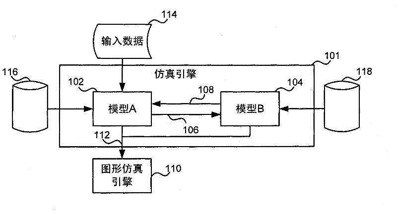
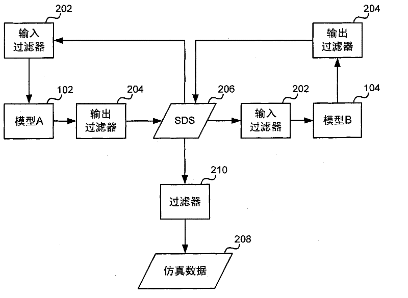
[0017] figure 1 is a schematic diagram of a system 100 for generating a graphical virtual environment, such as a simulated graphical world that can be used, for example, in a computer game or in a training / teaching tool. The system 100 includes a simulation engine 100 based on at least two scientific models 102 , 104 . Scientific models, such as scientific models 102, 104, generally include mathematical representations of the mechanisms or dynamics occurring in a p...


PUM


Abstract

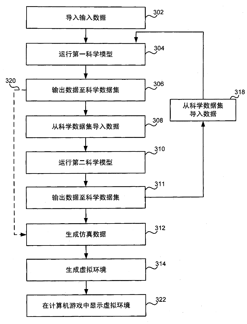
Use of scientific models to generate graphical virtual environments is described. In an embodiment at least two different scientific models are used. Input data which is representative of a real world environment is used by a first scientific model, such as a climate model, and data output by the first scientific model is then fed into a second, different, scientific model, such as an ecological model, in order to generate simulation data. The simulation data, which may, for example, detail the required population density of particular plant species and their size and age, is then used by a graphical simulation engine to generate a graphical virtual environment which may, for example, be used in a computer game such as a flight simulation game.

Description

Background technique [0001] Many computer game engines provide a 3D (three-dimensional) graphical simulation of the earth through which a user can navigate. The generation of the simulation environment involved a lot of manual work, including the manual positioning of ground elements such as mountains, lakes and forests. For a highly detailed view of a simulated environment, 3D objects can be manually placed in the environment; these objects can be individual trees or buildings, or a shape can be defined and simulated together with a collection of objects (such as trees) that will populate the shape The engine can then automatically fill the shape with objects from the defined collection. This process is very complex and time consuming, and has to be repeated for every new version of the game / simulation engine. [0002] To reduce the amount of manual work required, either aerial imagery or existing 3D models (such as Microsoft Virtual Earth TM ) to get the data. However,...

Claims


Application Information

Patent Timeline
IPC IPC(8): G06F9/455G06F9/44
CPCA63F2300/69A63F2300/64G09B9/00G09B9/301
Inventor A·海尔M·皮斯利V·卢特萨瑞夫
Owner MICROSOFT TECH LICENSING LLC
Learn More