Standby power cut-off device, its control method, and power supply device

A power cut-off and control method technology, applied to circuit devices, coupling devices, components of connecting devices, etc., can solve problems such as disconnection, standby power consumption, and inability to perform reservation functions.

Inactive Publication Date: 2011-11-30
SEOBY ELECTRONICS
View PDF5 Cites 33 Cited by
  • Summary
  • Abstract
  • Description
  • Claims
  • Application Information

AI Technical Summary

Problems solved by technology

However, the device will not start when the remote control is used to turn on the power, so the user needs to turn on the power switch installed on the electrical product himself, so the operation is more cumbersome
[0012] Moreover, various forms of standby power cutoff devices provided in the past have cut off the commercial power supply (main power supply) supplied to the electric product, so the reservation function included in the electric product cannot be used.
[0013] For example, when setting the wake-up alarm on the TV, if the standby power is cut off, the power supplied to the timer module will be cut off, and the scheduled time information will be deleted, so the scheduled function cannot be executed.
[0014] In addition, among household electrical appliances used at home, washing machines, dishwashers, microwave ovens, etc. without remote control, although the standby time is relatively long compared with the use time, the power plug is always connected.
[0015] Therefore, in the case of the above-mentioned electrical products, although the power switch is turned off during the non-use period, since the power supply device consumes more than 3W of power, unless the power plug is pulled out, the consumption of standby power will always occur.

Method used


Image

  • Standby power cut-off device, its control method, and power supply device
  • Standby power cut-off device, its control method, and power supply device
  • Standby power cut-off device, its control method, and power supply device

Examples


Embodiment Construction

[0078] Hereinafter, preferred embodiments of the present invention will be described in more detail with reference to the accompanying drawings. The following descriptions are only used to reveal the embodiments of the present invention, and the embodiments are not intended to limit the scope of rights of the present invention.

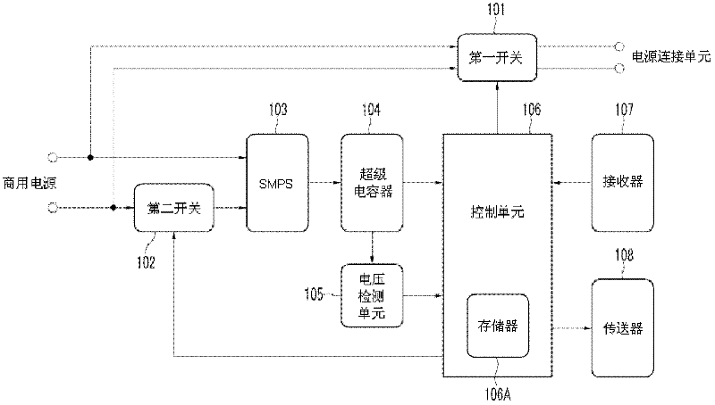
[0079] figure 1 is a schematic diagram showing the structure of the standby power cutoff device according to the first embodiment of the present invention.

[0080] The standby power cutting device of the present invention includes a first switch 101 , a second switch 102 , a switching power supply (SMPS) 103 , a supercapacitor 104 , a voltage detection unit 105 , a control unit 106 , a receiver 107 and a transmitter 108 .

[0081] The commercial power supply in the figure refers to the plug that is applicable to the multi-plug socket of the present invention connected to the socket on the wall of the building or another connection device extended by ...


PUM


Abstract

The present invention relates to a method for learning power on / off control data sent by a remote controller, and simultaneously controlling commercial power (main Power supply), thereby cutting off the standby power cut-off device and control method of the standby power generated on the electrical product. The standby power cut-off device of the present invention includes: a voltage conversion unit, which is used to convert a commercial power supply into a DC power supply; a charging and discharging unit, which is charged with the DC power supplied by the voltage conversion unit, and supplied as an operating power supply; A detection unit for detecting the charging level of the charging and discharging unit; a receiver for receiving power on / off control data of the remote controller; a control unit for turning on / off the power of the remote controller The control data is used to control the cut-off of the standby power of the designated electrical product; the first switch is used to perform on / off switching operation according to the control of the control unit to allow or cut off the commercial power supplied to the electrical product; According to the control of the control unit, the power on control data of the electric product is sent; the second switch performs on / off switching operation according to the control of the control unit to allow or disconnect the commercial power supplied to the voltage conversion unit.

Description

technical field [0001] The present invention relates to a standby power cut-off device and method thereof, and more particularly to a method for learning a power on / off control signal transmitted by a remote controller. When receiving the power on / off control signal from the remote controller, A standby power cutoff device, a control method thereof, and a power supply device that simultaneously control commercial power (main power supply) supplied to electric products to cut off standby power generated in the electric products. Background technique [0002] Usually, in order to use electrical products such as copiers, video recorders, microwave ovens, dishwashers, mobile phone chargers, computers, monitors, printers, fax machines, washing machines, air conditioners, etc. The extended multi-tap socket (Multi Tap) receives the supplied commercial power. [0003] Moreover, in the process of installing the electrical products, the plugs of the electrical products combined with ...

Claims


Application Information

Patent Timeline
Patent Type & Authority Applications(China)
IPC IPC(8): H01R13/70H02J9/00
CPCH01R13/665H02J9/005Y02B70/30Y04S20/20H01R13/10H01R13/70
Inventor 李成燮
Owner SEOBY ELECTRONICS
Why Eureka
Try Eureka