
Spraying valve

A valve body and nozzle technology, which is applied to coatings, devices that apply liquid to the surface, etc., can solve the problems of easy wear of the sealing ring gasket, slow dispensing speed, inconvenience, etc., so that the sealing structure is not easy to be damaged, and the function is better. Diversified, fast dispensing effect

Active Publication Date: 2013-02-20
SHENZHEN AXXON AUTOMATION
View PDF5 Cites 0 Cited by
  • Summary
  • Abstract
  • Description
  • Claims
  • Application Information

AI Technical Summary

Problems solved by technology

And in the process of assembling the assembly back to the spray valve after cleaning or replacing the assembly, the piston spring will produce a reverse force during the assembly process, often resulting in the need for two people to complete the assembly of the spray valve Circumstances occur that cause considerable inconvenience
Therefore, the disadvantages of the existing spray valves are that the sealing ring pad is easy to be worn, and the glue dispensing speed is slow, and the demand for glue with different proportions cannot be realized, resulting in low efficiency during construction.

Method used


Image

  • Spraying valve
  • Spraying valve

Examples


Embodiment 1

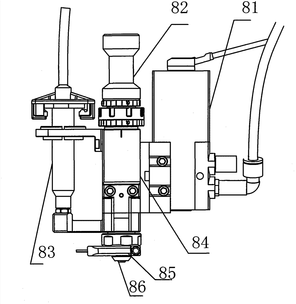
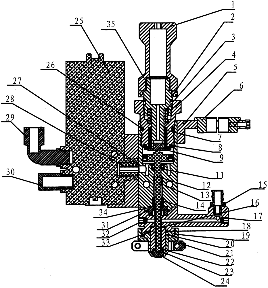
[0022] Such as figure 1 , figure 2 As shown in , a spraying valve includes a main valve body, a stroke adjustment device 82 arranged on the upper part of the main valve body, a feeding device 83 arranged on the side of the first body of the main valve body, and arranged on the side of the main valve body. The solenoid valve 81 on the second body side of the main valve body, a heating device 85 is arranged at the bottom of the main valve body, and a shower head 86 is arranged directly below the heating device 85;

[0023] The main valve body includes an upper valve body 26 and a lower valve body 31, the upper valve body 26 and the lower valve body 31 are connected by a fixing device, the upper valve body is provided with a first body cavity, and the head of a striker assembly 12 Arranged in the first body cavity, the middle part of the striker assembly 12 runs through the entire lower valve body, and the tail of the striker assembly 12 fits with the spray head arranged below ...

Embodiment 2

[0035] Such as figure 1 , figure 2 , as shown, on the basis of the above-mentioned implementation examples, the spray valve is usually used in conjunction with a glue dispenser or a desktop robot or a manipulator or other glue dispensing devices.

[0036] In the process of daily use, the spray valve is usually installed on the fixed end of the dispenser or the manipulator or the robot to complete the glue spraying process. In this example, as figure 1 , figure 2 The main valve body of a spraying valve is installed on the manipulator end of the dispensing robot, the stroke adjustment device 82 is arranged on the upper part of the main valve body, the feeding device 83 is arranged on the side of the first body of the main valve, and is arranged on the The solenoid valve 81 on the side of the second body of the main valve, a heating device 85 is arranged on the lower part of the main valve body, and a nozzle 86 is arranged directly below the heating device;

[0037] The main...


PUM


Abstract

The invention discloses a spraying valve which is characterized by comprising a main valve body, a stroke regulating device arranged at the upper part of the main valve body, a feeding device arranged at a first body side of the main valve, an electromagnetic valve arranged at a second body side of the main valve, a heating device arranged at the lower part of the main valve body and a spray head arranged under the heating device. The main valve body comprises an upper valve body and a lower valve body; the upper valve body is connected with the lower valve body through a fixing device; the upper valve body is provided with a first body cavity; the head of a striker component is arranged in the first body cavity, the middle part of the striker component penetrates through the whole lower valve body, and the tail of the striker component is jointed with a nozzle arranged below the heating device; an air inlet adaptor is arranged below the head of the striker component at the upper partof the upper valve body; the lower valve body is provided with a feeding hole module; and a feeding hole is at least arranged on the feeding hole module. The invention provides a glue dispensing spraying valve which rapidly and precisely dispenses glue, cuts off glue cleanly, and is in a sealing structure and hard to damage.

Description

technical field [0001] The invention relates to a fluid control device, in particular to a spray valve. Background technique [0002] Nowadays, the application of spraying valves for gluing components in the packaging process of various industrial products is quite common. Traditionally, the structure of spraying valves is mostly composed of four base screws and four upper cover screws. One upper cover, one piston spring, A device composed of structural components such as a piston, a body, a needle valve, a valve seat body and a tail seat. When a glue is input into the spray valve, and the needle valve is driven by the piston, the glue can be pushed out by the needle valve to achieve the purpose of dispensing. The multi-hole spray valve device is the screw A spray valve structure that bolts together many components. In the dispensing process of the spray valve, due to the continuous movement of the piston and the continuous impact of the needle valve, the glue will often s...

Claims


Application Information

Patent Timeline
Patent Type & Authority Patents(China)
IPC IPC(8): B05C5/00B05C11/00B05C11/10
Inventor 李高勇许文斌许洪涛楚善分
Owner SHENZHEN AXXON AUTOMATION
Learn More