A rotary engine and its rotor part

A rotary engine and rotor technology, applied in the direction of combustion engine, machine/engine, internal combustion piston engine, etc., can solve the problems of not being able to take advantage of the advantages of the rotary engine, limit the output speed of the rotary engine, and the complicated structure of the rotary engine, so as to achieve convenient installation and application , simple structure, high possibility of effect

Inactive Publication Date: 2011-12-07
HUBEI NEW TORCH SCIENCE & TECHNOLOGY CO LTD
View PDF6 Cites 3 Cited by
  • Summary
  • Abstract
  • Description
  • Claims
  • Application Information

AI Technical Summary

Problems solved by technology

Based on the above reasons, in order to maintain the effective air intake, it is necessary to limit the rotation speed of the casing; the limitation on the rotation speed of the casing limits the output speed of the rotary engine, and cannot take advant

Method used


Image

  • A rotary engine and its rotor part
  • A rotary engine and its rotor part
  • A rotary engine and its rotor part

Examples


Embodiment Construction

[0040] The present invention will be described in detail below in conjunction with the accompanying drawings. The description in this part is only exemplary and explanatory, and should not have any limiting effect on the protection scope of the present invention.

[0041] For the convenience of description, the following describes the rotor part while describing the overall structure of the rotary engine, and does not describe the rotor part separately.

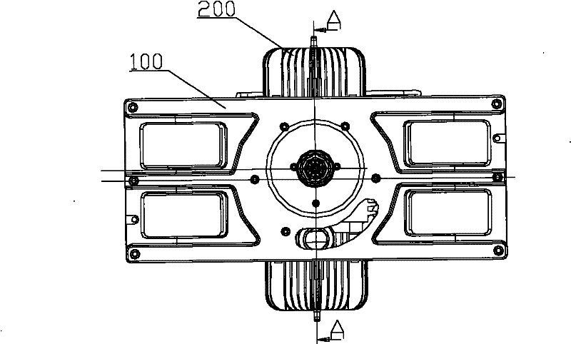
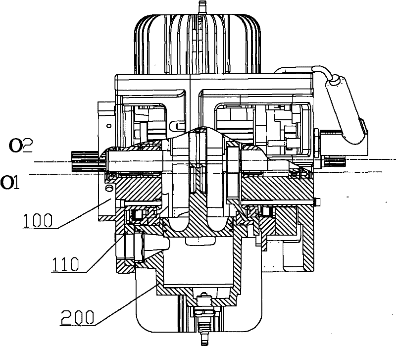
[0042] Please refer to figure 2 and image 3 , figure 2 is a schematic structural diagram of a rotary engine provided by an embodiment of the present invention, image 3 yes figure 2 Middle A-A sectional view. The rotary engine provided in the embodiment includes a stator part 100 and a rotor part 200 , the stator part 100 is fixed to a predetermined foundation, and the rotor part 200 can rotate relative to the stator part 100 . The structure of the rotor portion 200 will be described in detail below.

[0043] Please...


PUM


Abstract

The invention discloses a rotor engine and a rotor part thereof. The rotor part of the rotor engine comprises a shell, a crankshaft and a piston. An air inflow channel and an exhaust channel communicated with the cylinder barrel of the shell are arranged on the shell. Both the exhaust channel and the air inflow channel are positioned in the side wall of a cylinder. A distance is predetermined between an inner opening of each of the exhaust channel and the air inflow channel and the topmost part of the cylinder. In the rotor part of the rotor engine provided by the invention, because both the exhaust channel and the air inflow channel are positioned in the side wall of the cylinder, and the distances is predetermined between the inner opening of each of the exhaust channel and the air inflow channel and the topmost part of the cylinder, when the rotor engine works, at least one part of air in the cylinder barrel cannot flow outwards through the exhaust channel under the action of centrifugal force, and the air inflow resistance which is increased because of the centrifugal force can be reduced, therefore, the rotor engine can be ensured to achieve higher effective air inflow amount, and the premise for increasing the output power and the output rotation speed of the rotor engine is provided.

Description

technical field [0001] The present invention relates to an engine, in particular to a rotor part of a rotary engine, and also to a rotary engine comprising the rotor part. Background technique [0002] Currently, various types and structures of engines have been disclosed. Among them, the technology of the piston engine is the most mature and the most widely used; although the triangular rotor engine has been applied in the market, the scope of application is still very limited. Swiss patent literature CH71501 discloses a rotary engine, please refer to figure 1 , which is a structural schematic diagram of the rotary engine disclosed in Swiss Patent Document CH71501. This rotary motor comprises a stator part (not shown in the figure) and a rotor part, and the rotor part comprises a casing 10, a crankshaft 20 and two pistons, and the casing 10 is rotatably mounted on the stator part, and the rotation axis of the casing 10 is O1. A cylinder 11 is formed inside the housing 1...

Claims


Application Information

Patent Timeline
IPC IPC(8): F02B55/02F02B53/04F02B55/12
CPCY02T10/17Y02T10/12
Inventor 吴少伟
Owner HUBEI NEW TORCH SCIENCE & TECHNOLOGY CO LTD
Why Eureka
Try Eureka