
fuel injection control system

A fuel injection and control system technology, applied in the direction of fuel injection control, electrical control, engine control, etc., can solve the problems of too rich and too lean combustion state, and cannot always monitor the oxygen sensor, etc., to prevent excessive enrichment or delease Effect

Active Publication Date: 2011-12-07
HONDA MOTOR CO LTD
View PDF4 Cites 7 Cited by
  • Summary
  • Abstract
  • Description
  • Claims
  • Application Information

AI Technical Summary

Problems solved by technology

[0005] However, in the technique described in Patent Document 1, the limit value of the air-fuel ratio feedback correction coefficient increases every time of warm-up operation, so there is a possibility that if the feedback correction amount becomes too large or hours, the warm-up operation will be performed in the state of over-rich or under-lean
Also, when the increment of the limit value is determined, any influence exerted on the air-fuel ratio by the height of the vehicle's use position, the accuracy of parts of the vehicle, changes at the time of installation, etc. is no longer considered.
In addition, the technique described in Patent Document 1 can only periodically perform failure checking, and cannot always monitor the state of the oxygen sensor because the failure checking is performed by monitoring the current generated by applying a reverse voltage to the oxygen sensor
In addition, if the learning of the air-fuel ratio feedback correction coefficient is adapted to be prohibited when the fault inspection is performed, it may happen that the output value of the oxygen sensor just before the fault inspection is started is used for the air-fuel ratio feedback control during the fault inspection, thereby causing the In the event that a sensor fails just before the fault check is started, there is a possibility that the combustion state during the fault check will become too rich or too lean

Method used

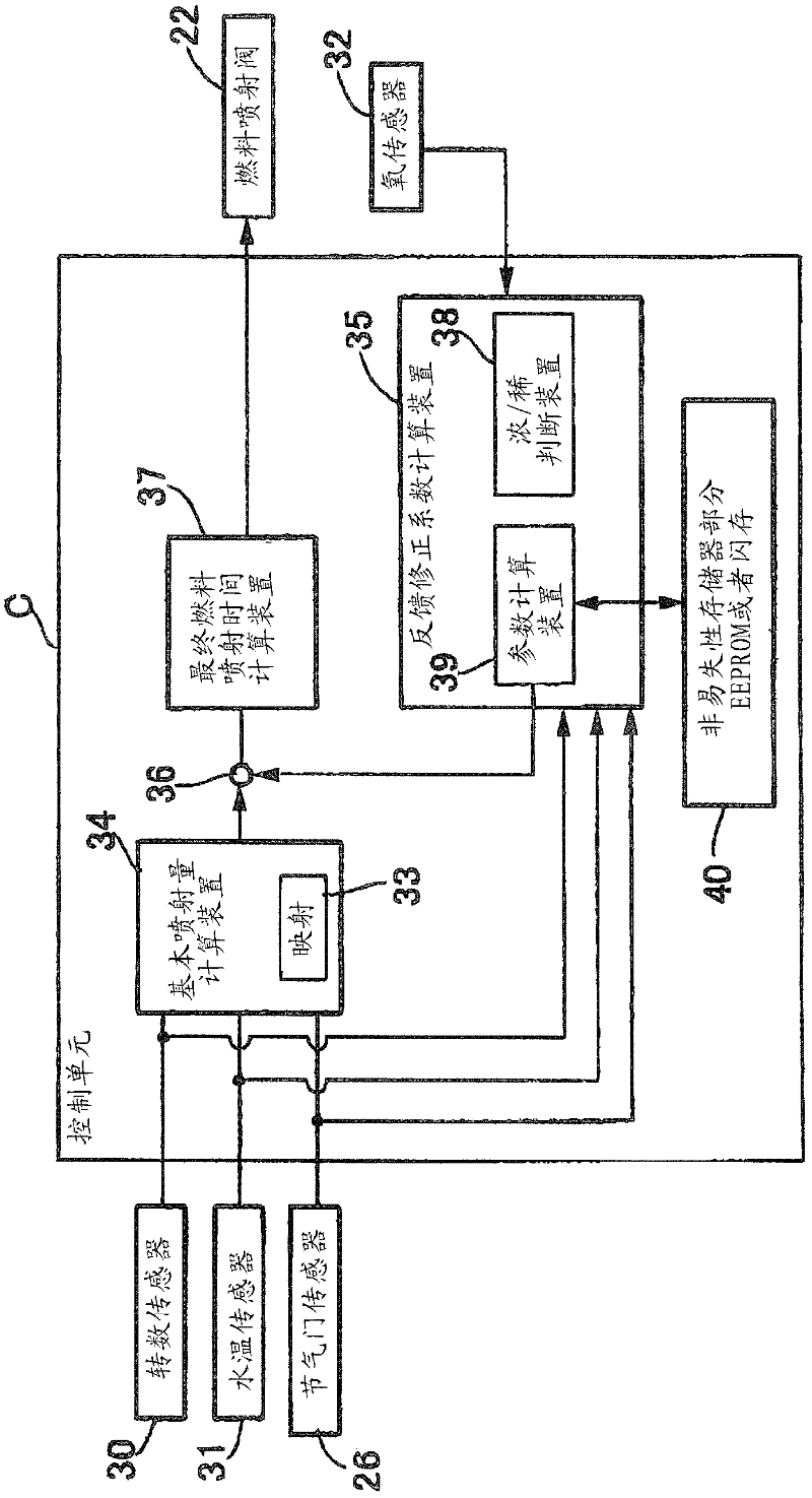
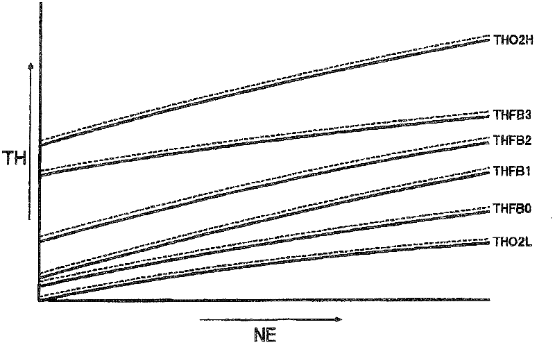

Image

  • fuel injection control system
  • fuel injection control system
  • fuel injection control system

Examples


Embodiment Construction

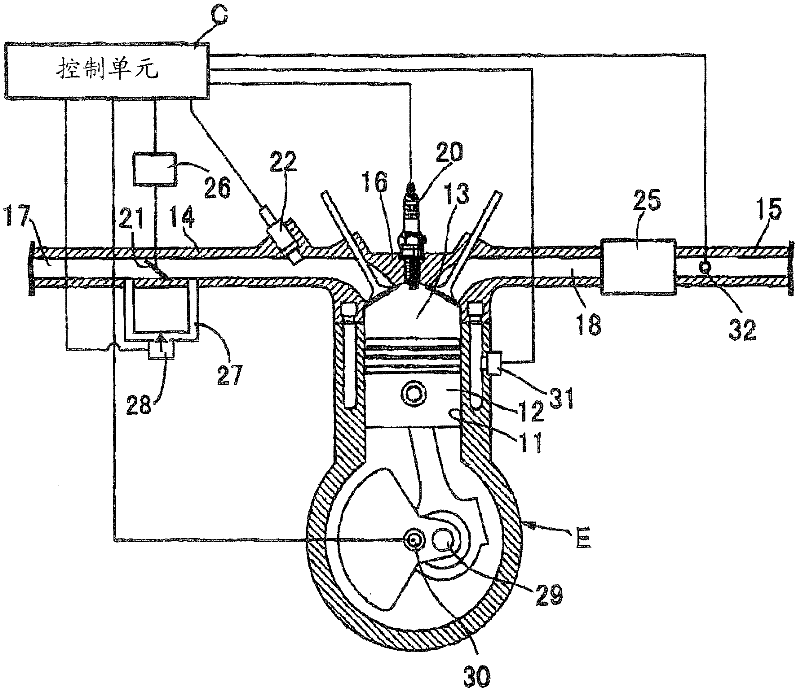
[0074] Preferred embodiments of the present invention will be described in detail with reference to the accompanying drawings. figure 1 is a block diagram showing the configuration of a fuel injection control system for an internal combustion engine according to an embodiment of the present invention. A piston 12 is slidably fitted in a cylinder bore 11 of a water-cooled internal combustion engine E mounted on a motorcycle. An intake device 14 for supplying an air-fuel mixture to a combustion chamber 13 and an exhaust device 15 for exhausting exhaust gas from the combustion chamber 13 are connected to a cylinder head 16 of the internal combustion engine E with an upper portion of the piston 12 facing the combustion chamber 13 . An intake passage 17 is formed in the intake device 14 , and an exhaust passage 18 is formed in the exhaust device 15 . A spark plug 20 with a front end facing the combustion chamber 13 is attached to the cylinder head 16 .

[0075] The intake device ...


PUM


Abstract

To provide a fuel injection control system which properly sets a limit value of an air-fuel ratio feedback correction value, thereby making a good air-fuel ratio feedback control possible. While a variation rate of an output value of an oxygen sensor (32) is changed from the positive to the negative or from the negative to the positive predetermined times after a power source of a vehicle is turned on, a control unit (C) sets a first limit range (L1) for an air-fuel ratio feedback correction factor (K02) as an upper / lower limit value which have a predetermined upper / lower width, in which the output value of the oxygen sensor (32) detected in a stoicshiometric air-fuel ratio state is a reference value (B1), and which is allowed to be used for calculating a correction injection quantity (T1). After a variation rate of the output value of the oxygen sensor (32) is changed from the positive to the negative or from the negative to the positive predetermined times, the air-fuel ratio feedback correction factor (K02) that is calculated when the variation rate is changed the predetermined times is regarded as a reference value (B2), and a second limit range (L2) which has a predetermined upper / lower width from the reference value (B2) and is narrower than the first limit range (L1) is set.

Description

technical field [0001] The present invention relates to a fuel injection control system, and more particularly, to a fuel injection control system adapted to perform air-fuel ratio feedback control based on an output of an air-fuel ratio sensor. Background technique [0002] In the past, there has been known a fuel injection system in which feedback control of the fuel injection amount based on the air-fuel ratio is adapted for combustion in an internal combustion engine in a region close to the theoretical (theoretical) air-fuel ratio, so that The air-fuel ratio is detected by an air-fuel ratio sensor (oxygen sensor) provided at the exhaust pipe. When such air-fuel ratio feedback control is applied, if the feedback correction coefficient, that is, the feedback correction amount becomes too large or too small for any reason, there is a possibility of excessive enrichment or leaning. Therefore, in order to prevent this situation, it is considered to set a limit value for the...

Claims


Application Information

Patent Timeline
Patent Type & Authority Applications(China)
IPC IPC(8): F02D41/14F02D41/22F02D41/30
CPCF02D41/1438F02D41/065F02D41/22
Inventor 西冈修村上胜宪大西谦太岸信之高野祐纪
Owner HONDA MOTOR CO LTD
Learn More