Moving object detection device and moving object detection method

A detection device and detection method technology, applied in image data processing, instruments, calculations, etc., can solve problems such as difficult high reliability, unable to detect moving objects, etc.

Inactive Publication Date: 2011-12-07
TOSHIBA ALPINE AUTOMOTIVE TECHNOLOGY CORP
View PDF6 Cites 28 Cited by
  • Summary
  • Abstract
  • Description
  • Claims
  • Application Information

AI Technical Summary

Problems solved by technology

[0005] In the existing vehicle-mounted moving object detection device, since the camera itself moves, even if it is a static object, it will become a dynamic image on the screen, so it is difficult to judge whether it is a static object or a moving object with high reliability. body
Even though moving objects are detected in certain scenes, moving objects are not detected in other scenes

Method used


Image

  • Moving object detection device and moving object detection method
  • Moving object detection device and moving object detection method
  • Moving object detection device and moving object detection method

Examples


no. 1 approach

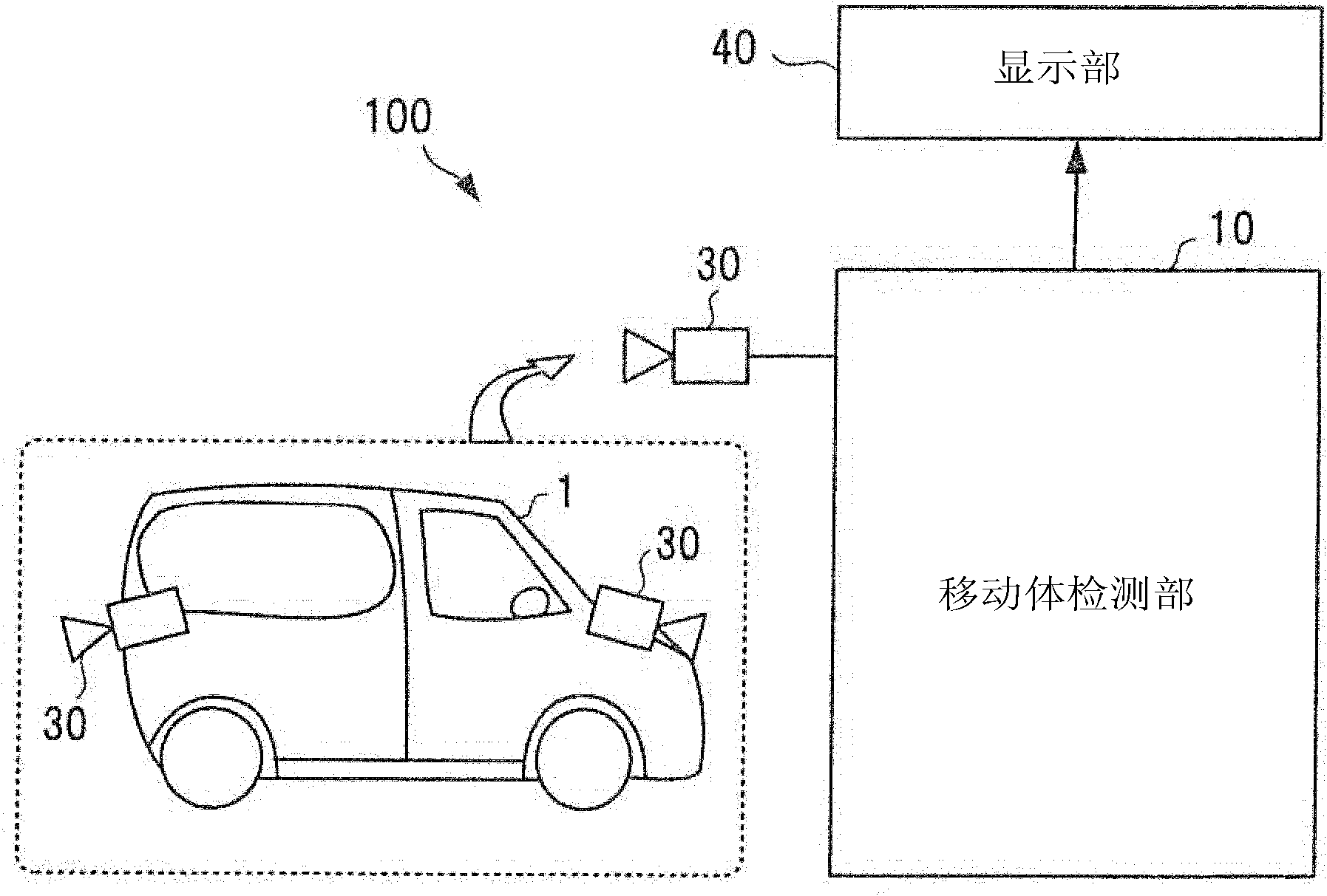
[0028] figure 1 It is a block diagram showing the configuration of a moving body detection device 100 according to an embodiment of the present invention. in figure 1 Among them, the moving body detection unit 10 is used to process an image captured by a camera 30 mounted on the vehicle 1 to detect the moving body, and display the detection result on the display unit 40. The camera 30 is installed on the vehicle 1 and is used to capture images around the vehicle. figure 1 An example in which cameras 30... are installed in the front and rear of the vehicle 1 and the like is shown.

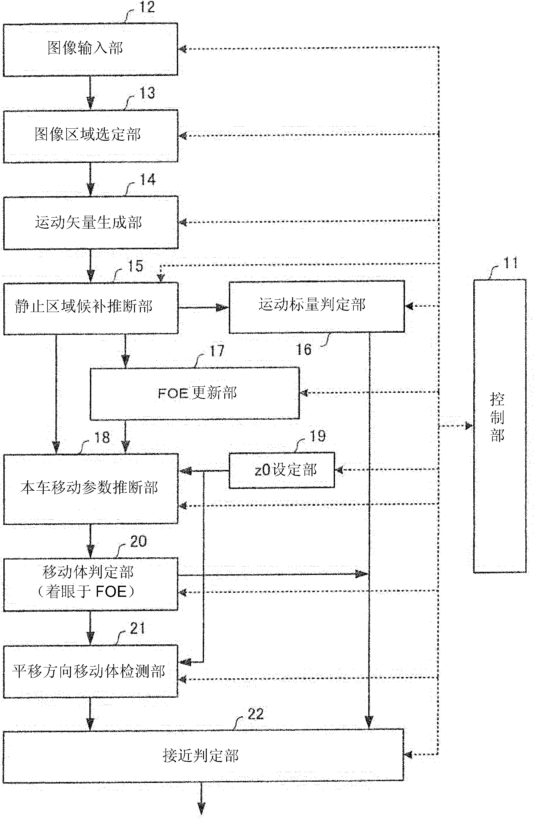
[0029] figure 2 It is a block diagram showing the detailed configuration of the moving body detection unit 10. The moving body detection unit 10 includes: a control unit 11 for controlling the action of the moving body detection unit 10; an image input unit 12 for loading camera images; an image area selection unit 13 for selecting a The image area of ​​the image information for which the detection p...

no. 2 approach

[0090] Next, refer to Picture 10 The moving body detection device according to the second embodiment will be described. In the second embodiment, the moving body determining unit 20 focusing on FOE is replaced with a motion vector predicting unit 23, and the translational moving body detecting unit 21 is replaced with a moving body determining unit 24.

[0091] As in the first embodiment, the vehicle movement parameter estimation unit 18 outputs the rotation components Rx, Ry, Rz, and the average translation components Tzm, Txm, and Tym. The motion vector predictor 23 uses Tzm / z0, Txm / z0, and Tym / z0 instead of Tz / z, Tx / z, and Ty / z, and calculates prediction vectors u'and v'according to equations (1) to (4).

[0092] The motion detection unit 24 compares the actual motion vectors u and v with the predicted vectors u'and v', and determines that it is a moving body when the degree of coincidence is low. In the case of a vehicle-mounted camera, since Tx and Ty are often small, Tx / z, ...

no. 3 approach

[0094] Next, the moving body detection device according to the third embodiment will be explained. As for the vehicle-mounted camera, in the case of a fish-eye camera or a vehicle-mounted camera with a viewing angle of 180 degrees or more than a camera like a camera with a convex mirror, since a non-linear projection method is used, a linear plane is used as the The premise is that the method of analysis cannot detect moving objects.

[0095] Therefore, in the third embodiment, it is possible to detect a moving body even if it is a non-linear image captured by a camera with a large angle of view of the shooting range.

[0096] Expressing figure 1 In the block diagram of the structure of the moving body detection device 100 shown, the moving body detection unit 10 processes the image taken by the camera 30 mounted on the vehicle 1 and detects the moving body, and then displays the detection result on the display unit 40 .

[0097] The camera 30 is an ultra-wide-view camera with a vi...


PUM


Abstract

An apparatus for detecting a moving object includes: an image input unit that inputs a camera image; a motion vector generation unit that generates motion vectors of a plurality of points P in the image; an estimation unit that estimates rotational components of vehicle movement parameters as being equal to the inclination from each point P to a vanishing point when the inclination of the motion vector of each point P is corrected by the rotational components; and a determination unit that corrects the inclination of the motion vector of a given point Q in the image, and detects the existence of a moving object that moves in a direction different from the vehicle movement direction when the coincidence degree between the inclinations is low, while detects the existence of an object that radially moves toward the vanishing point when the coincidence degree of the inclinations is high.

Description

[0001] Cross reference of related applications [0002] This application is based on Japanese Patent Application No. 2010-128974 (application date: 6 / 4 / 2010) and Japanese Patent Application No. 2010-139543 (application date: 6 / 18 / 2010), and the application enjoys priority benefits. This application includes the entire content of the application by referring to the application. Technical field [0003] Embodiments of the present invention relate to a moving body detection device and a moving body detection method that detect a moving body by capturing an image of the periphery of the vehicle with a camera mounted on the vehicle, and then processing the camera image. Background technique [0004] Previously, an image display device for a vehicle is known in which a plurality of cameras are installed on the vehicle to take pictures of the front, rear, or side of the vehicle, detect moving objects based on the captured images, and approach the vehicle. The moving body of the car is dis...

Claims


Application Information

Patent Timeline
Patent Type & Authority Applications(China)
IPC IPC(8): G06T7/20
CPCG06T2207/10016G06T2207/30244G06T5/006G06T2207/30261G06T7/0042G06T7/20G06T7/73
Inventor 川井清幸
Owner TOSHIBA ALPINE AUTOMOTIVE TECHNOLOGY CORP
Why Eureka
Try Eureka