Magnetic resonance imaging device

A magnetic resonance image, magnetic resonance technology, applied in the direction of measuring devices, magnetic therapy, measuring magnetic variables, etc.

Active Publication Date: 2011-12-14
TOSHIBA MEDICAL SYST CORP
View PDF7 Cites 4 Cited by
  • Summary
  • Abstract
  • Description
  • Claims
  • Application Information

AI Technical Summary

Problems solved by technology

The static magnetic field coil forms a static magnetic field

Method used


Image

  • Magnetic resonance imaging device
  • Magnetic resonance imaging device
  • Magnetic resonance imaging device

Examples


Embodiment Construction

[0027] Hereinafter, this embodiment will be described with reference to the drawings.

[0028] (Configuration of Magnetic Resonance Diagnosis Apparatus 1 )

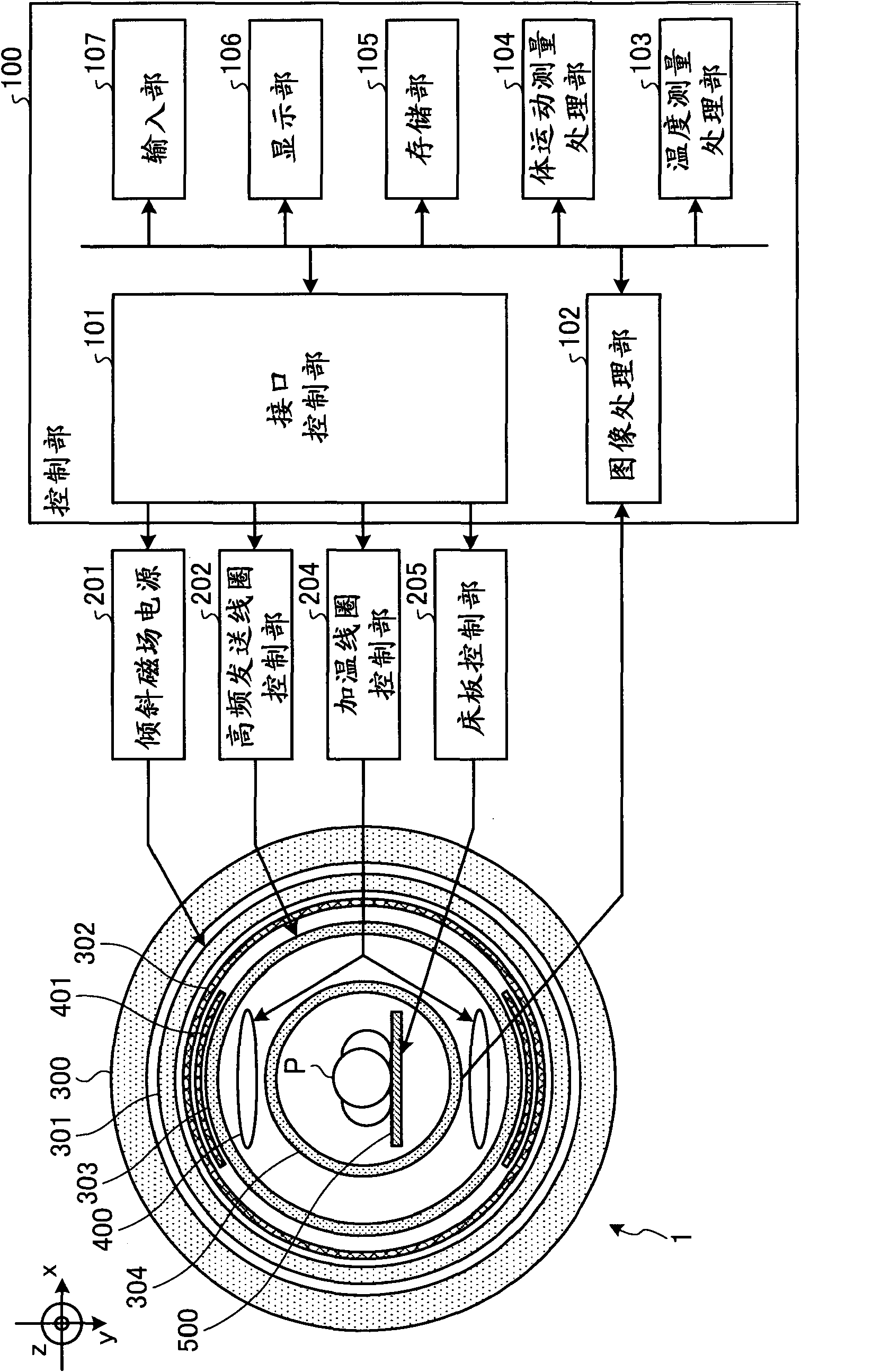
[0029] figure 1 It is a block diagram showing the configuration of the magnetic resonance diagnostic apparatus 1 according to the present embodiment. like figure 1 As shown, the magnetic resonance diagnostic apparatus 1 combines the control unit 100, the gradient magnetic field power supply 201, the high frequency transmission coil control unit 202, the heating coil control unit 204, the bed board control unit 205, the static magnetic field magnet 300, the gradient magnetic field coil 301, the transmission coil The RF shield 302 , the high frequency transmitting coil 303 , the high frequency receiving coil 304 , the heating coil 400 , the heating coil RF shield 401 and the bed board 500 are composed. In addition, the configuration of the magnetic resonance diagnostic apparatus 1 is not limited to this, and constituent ...


PUM


Abstract

A magnetic resonance diagnostic apparatus is configured in such a manner that: a high-frequency transmission coil transmits a high-frequency electromagnetic wave at a magnetic resonance frequency to an examined subject; a heating coil performs a heating process by radiating a high-frequency electromagnetic wave onto the examined subject at a frequency different from the magnetic resonance frequency; based on a magnetic resonance signal, a measuring unit measures the temperature of the examined subject changing due to the high-frequency electromagnetic wave radiated by the heating coil; and a control unit exercises control so that the measuring unit measures the temperature while the heating coil is performing the heating process, by ensuring that the transmission of the high-frequency electromagnetic wave by the high-frequency transmission coil and the radiation of the high-frequency electromagnetic wave by the heating coil are performed in parallel.

Description

[0001] Cross References to Related Applications [0002] This application is based on and claims priority from prior Japanese Patent Application No. 2010-112454 filed on May 14, 2010 and prior Japanese Patent Application No. 2011-80817 filed on March 31, 2011, all of which The contents are incorporated by reference in this application. technical field [0003] The present embodiment relates to a magnetic resonance diagnostic apparatus that collects ecological information inside a subject by using a magnetic resonance phenomenon. Background technique [0004] In recent years, for the treatment of prostatic hyperplasia, cancer, etc., hyperthermia therapy, in which a tumor of a subject is heated, denatured and necrotic has been used. In order to perform such warming therapy more efficiently, it is necessary to know the position of the warming region in the subject and the temperature of the warming region. [0005] In order to grasp the position and temperature of the heating...

Claims


Application Information

Patent Timeline
Patent Type & Authority Applications(China)
IPC IPC(8): A61B5/055
CPCA61N1/403A61B5/1128G01R33/4804A61B5/0555G01R33/4808A61N2/004A61B5/015A61B5/055
Inventor 坂仓良知杉浦聪吉田智幸梁岛隆岩佐政晃加藤裕喜多村浩司野上和人田中秀和佐藤诚久原重英川上毅人安原康毅杉本博
Owner TOSHIBA MEDICAL SYST CORP
Why Eureka
Try Eureka