Method for transmitting location based service -reference signal in wireless communication system and apparatus therefor

a wireless communication system and location-based service technology, applied in the field of wireless communication systems, can solve the problems of time delay and reception power of lbs-rs, and achieve the effect of reducing the number of times of lbs-rs

Active Publication Date: 2010-09-23
LG ELECTRONICS INC
View PDF5 Cites 94 Cited by
  • Summary
  • Abstract
  • Description
  • Claims
  • Application Information

AI Technical Summary

Benefits of technology

[0020]As can be seen from the embodiments of the present invention, a base station for use in a wireless communication system can effectively transmit an LBS-RS.

Problems solved by technology

In addition, when establishing the LBS-RS transmitted from each cell to the MS, a reception power and time delay of the LBS-RS must be considered.

Method used


Image

  • Method for transmitting location based service -reference signal in wireless communication system and apparatus therefor
  • Method for transmitting location based service -reference signal in wireless communication system and apparatus therefor
  • Method for transmitting location based service -reference signal in wireless communication system and apparatus therefor

Examples


first embodiment

[0061]A method for compensating for a path loss encountered when a plurality of cells transmit LBS-RS to an MS will hereinafter be described with reference to the first embodiment of the present invention.

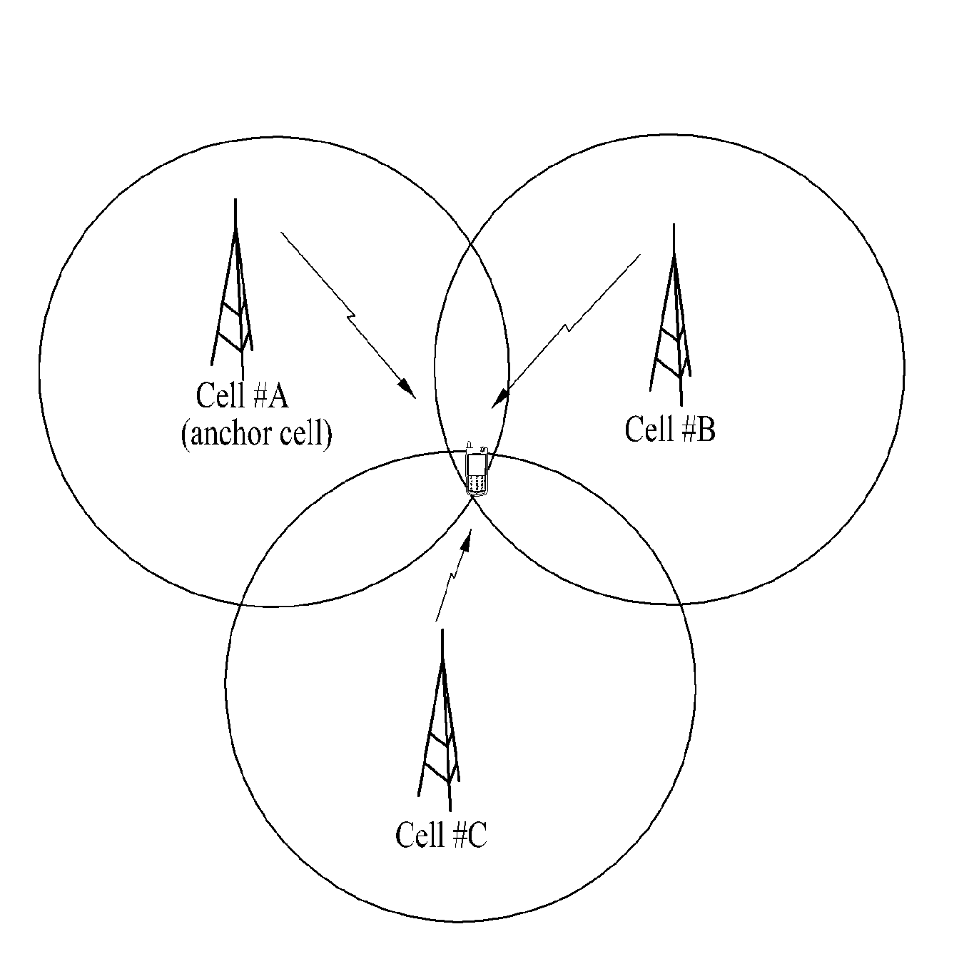
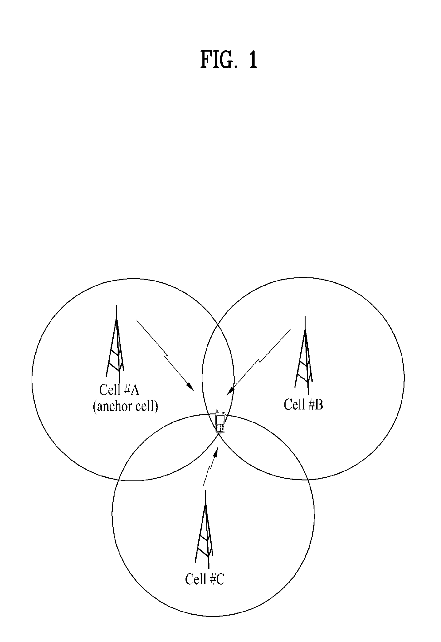
[0062]FIGS. 6 and 7 illustrate a path loss encountered in signals received from a plurality of cells according to the present invention. In the above-mentioned process for measuring the MS location, there is a need to receive LBS-RSs from one or more cells (preferably, three or more cells). For convenience of description, the following considers only two cells, that is, a serving cell and a target cell.

[0063]Under the condition that the MS is connected to a serving cell, if the MS receives LBS-RSs from both the serving cell and the target cell, the following first and second cases may be used.

[0064]The first case is shown in FIG. 6. In FIG. 6, a path loss derived from the serving cell (cell #A) is similar to another path loss derived from the target cell (cell #B). The second case ...

second embodiment

[0068]The second embodiment of the present invention is devised to prevent interference between signals caused by a propagation delay of the LBS-RS transmitted from each cell.

[0069]First, propagation delay will hereinafter be described in detail. FIG. 8 is a conceptual diagram illustrating a propagation delay generated in a signal transmitted from a plurality of cells according to the second embodiment of the present invention.

[0070]Referring to FIG. 8, even though a first cell A and a second cell B have transmitted respective transmission (Tx) signals at the same time, it should be noted that the transmission (Tx) signals may be received in the MS at different time points according to individual propagation paths. Specifically, FIG. 8 illustrates an exemplary case wherein the MS is located close to the cell A, and a signal received from the cell B is higher than another signal received from the cell A. Accordingly, signals received from different cells may be received in the MS at ...

third embodiment

[0077]In order to allow the MS to measure a delay time of a signal transmitted from the target cell without detecting a boundary between subframes of the same signal, the serving cell may inform the MS of both the target cell ID and a rough subframe time point. In this case, the rough subframe timing may be determined by a target cell ID, a subframe number of a serving cell, and a system frame number. In addition, the serving cell may inform the MS of not only a bandwidth of the LBS-RS transmitted from the target cell but also the location of a frequency where the LBS-RS is allocated. By means of the above-mentioned information, a search process indicating which one of target cells participates in location measurement and a synchronization process for signal measurement may be omitted from the LBS-RS detection process of the MS.

[0078]Information required for measuring the MS location may be broadcast by the serving cell. In this case, information being broadcast by the serving cell ...


PUM


Abstract

A method for allowing a mobile station to detect a Location Based Service-Reference Signal (LBS-RS) in a wireless communication system is disclosed. The method includes receiving LBS-RS setup information of at least one target cell participating in location measurement from a serving cell, acquiring a frequency offset value of the target cell using the LBS-RS setup information, and detecting the LBS-RS transmitted from the target cell using the LBS-RS setup information and the frequency offset value. In addition, the method further includes measuring a reception delay time of the detected LBS-RS, and transmitting a reception delay time to the serving cell.

Description

[0001]This application claims the benefit of U.S. Provisional Patent Application Nos. 61 / 161,041, filed on Mar. 17, 2009, 61 / 161,396, filed on Mar. 18, 2009, 61 / 162,330, filed on Mar. 22, 2009 and 61 / 165,522, filed on Apr. 1, 2009, and Korean Patent Application No. 10-2009-0132749, filed on Dec. 29, 2009, which is hereby incorporated by reference as if fully set forth herein.BACKGROUND OF THE INVENTION[0002]1. Field of the Invention[0003]The present invention relates to a wireless communication system, and more particularly to a method for transmitting a reference signal which allows a base station of a wireless communication system to provide a location based service, and an apparatus for the method.[0004]2. Discussion of the Related Art[0005]Conventionally, a geographical location of a mobile station is calculated by measuring time delays of signals transmitted from a plurality of cells. Therefore, three or more signals are needed to measure the location of the mobile station. Eve...

Claims


Application Information

Patent Timeline
Patent Type & Authority Applications(United States)
IPC IPC(8): H04L27/28H04W64/00
CPCH04L5/0023H04L5/0053H04L5/0092H04L25/0204H04L27/2657H04L25/0228H04L27/2613H04L27/2655H04L25/0216H04W64/00H04W4/029H04W4/023H04W4/025
Inventor LEE, DAE WONYUN, YOUNG WOOKIM, BYUNG HOONAHN, JOON KUIKIM, KI JUNKIM, BONG HOE
Owner LG ELECTRONICS INC
Why Eureka
Try Eureka