
An anti-twist device for a crane wire rope

An anti-twist and steel wire rope technology, which is applied in the field of steel wire ropes in the hoisting mechanism of large-lift cranes, can solve the problems that torsional stress cannot be released and affects the service life of steel wire ropes, and achieves the effect of improving service life

Inactive Publication Date: 2011-12-14
TAIYUAN HEAVY IND
View PDF6 Cites 12 Cited by
  • Summary
  • Abstract
  • Description
  • Claims
  • Application Information

AI Technical Summary

Problems solved by technology

[0003] The purpose of the present invention is to overcome the above shortcomings of the prior art, provide an anti-twist device for the steel wire rope of the crane, and solve the problem that the torsional stress generated by the steel wire rope of the existing crane hoisting mechanism cannot be released due to the rotation direction and winding, which affects the service life of the steel wire rope question

Method used


Image

  • An anti-twist device for a crane wire rope
  • An anti-twist device for a crane wire rope
  • An anti-twist device for a crane wire rope

Examples


Embodiment Construction

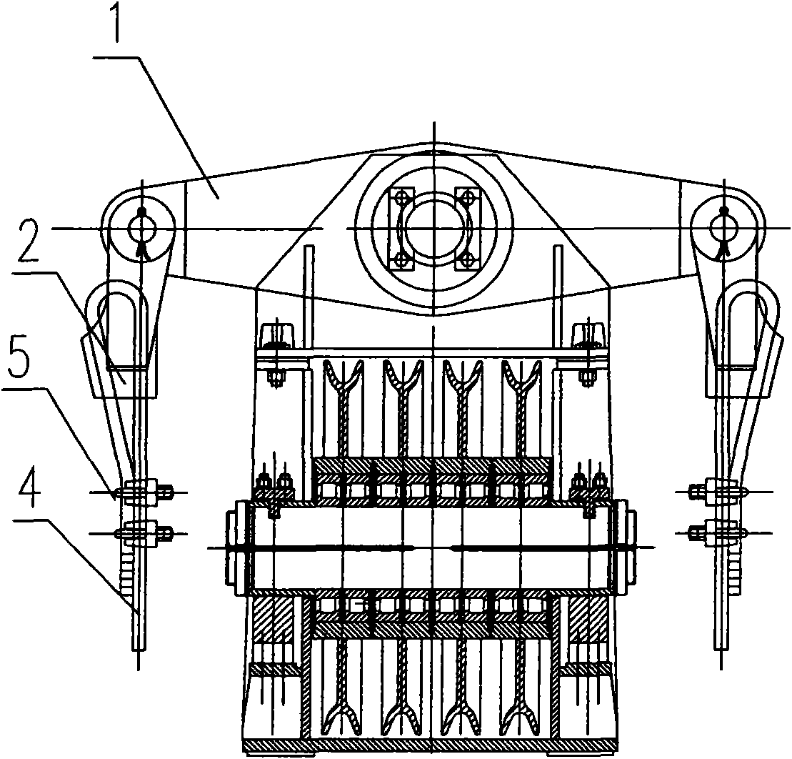
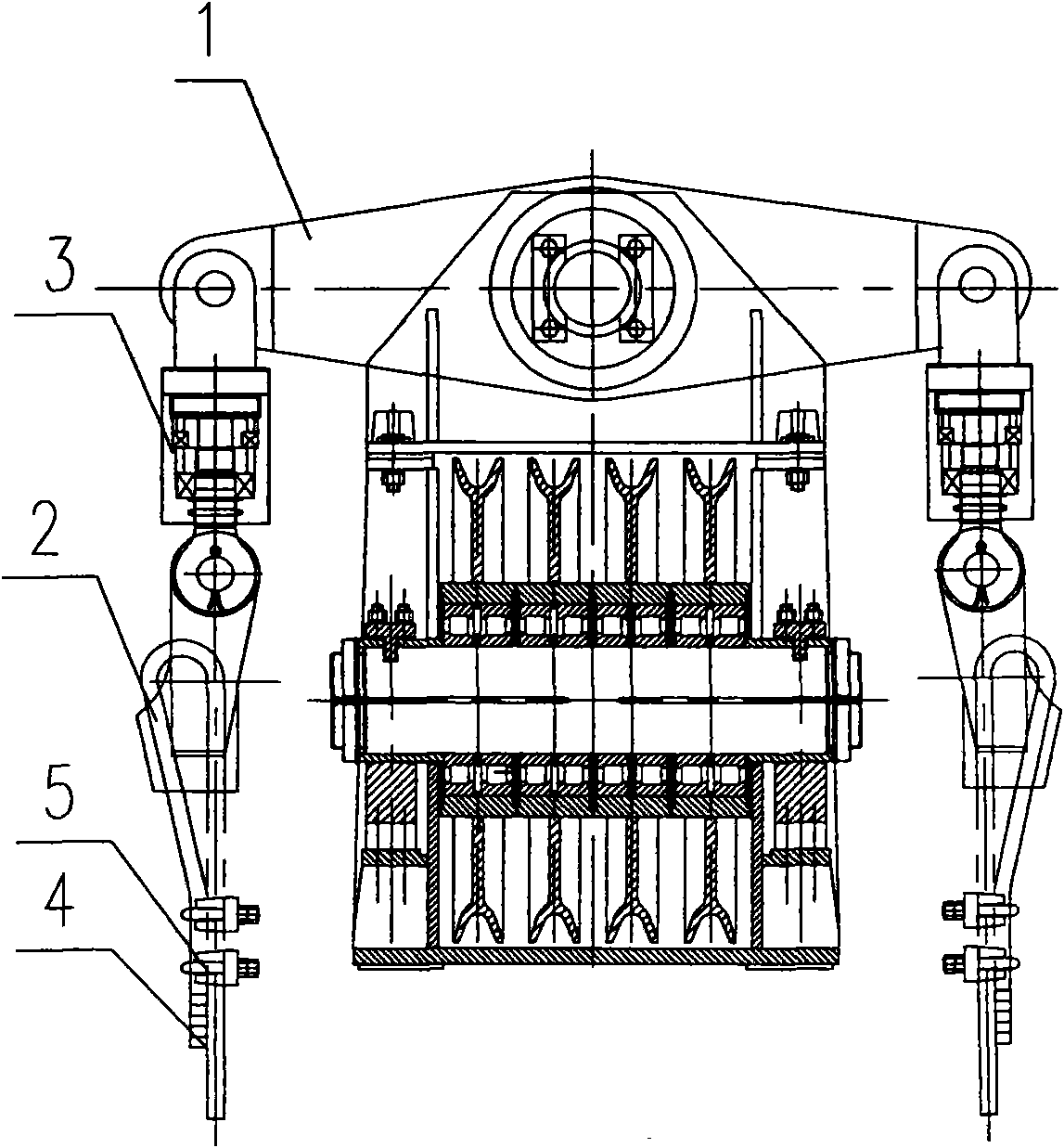
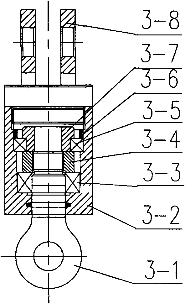
[0014] Such as figure 2 , 3 As shown, one end of the anti-twist device 3 of the two crane wire ropes is respectively hinged to the two ends of the balance arm 1 of the pulley device on the hoisting mechanism of the crane, and the other ends of the two anti-twist devices 3 are respectively hinged to the wedge joint 2, so The wedge-shaped joint 2 and the wire rope 4 are fixedly connected by the wire rope clip 5; the two anti-twist devices 3 are composed of a trunnion 3-1, a housing 3-2, a thrust bearing 3-3, a nut 3-4, a radial Bearing 3-5, inner bushing 3-6, outer bushing 3-7, seat body 3-8; the seat body 3-8 is hinged at the end of the balance arm 1, and the trunnion 3- 1 and the ear hole of the wedge joint 2 are hinged, and the shaft body of the trunnion 3-1 passes through the thrust bearing 3-3, the nut 3-4, the radial bearing 3-5, the inner bushing 3- 6. The outer shaft sleeve 3-7 is installed in the housing 3-2.

[0015] The thrust bearing 3-3 is set on the shaft body ...


PUM


Abstract

The utility model relates to an anti-rotation device for a crane steel wire rope, which relates to a steel wire rope for a hoisting mechanism of a crane with a large lift. The invention solves the problem that the torsional stress generated by the steel wire rope of the hoisting mechanism of the existing crane cannot be released due to the direction of rotation and winding, and the service life of the steel wire rope is affected. One ends of the two anti-twist devices are respectively hinged to both ends of the balance arm of the pulley device on the hoisting mechanism of the crane, and the other ends of the two anti-twist devices are respectively hinged to a wedge-shaped joint, and the wedge-shaped joint is fixedly connected to the wire rope; The two anti-rotation devices are composed of trunnions, shells, thrust bearings, nuts, radial bearings, inner and outer bushings, and seats; the seats are hinged at the ends of the balance arms, so that The ear hole of the trunnion is hinged with the ear hole of the wedge joint, and the shaft body of the trunnion is installed in the housing through the thrust bearing, nut, radial bearing, inner and outer bushings. The invention is suitable for application in the hoisting mechanism of a crane with a large lift.

Description

technical field [0001] The invention belongs to hoisting and transporting machinery, in particular to a steel wire rope for a hoisting mechanism of a large-lift crane. Background technique [0002] At present, the upper pulley device of the commonly used crane hoisting mechanism is as follows: figure 1 As shown, the two ends of the balance arm 1 are hinged with the wedge joint 2, and the wedge joint 2 and the wire rope 4 are fixedly connected by the wire rope clip 5 (the wire rope cannot rotate). Since the steel wire rope 4 cannot rotate relative to the balance arm 1, the torsional stress produced by the steel wire rope due to the direction of rotation and winding cannot be released. For cranes with low head, this torsional force will not have a great impact on the wire rope, but the situation is different for cranes with high head. Due to the high head and the long wire rope, the torsional stress caused by the rotation of the wire rope itself and the winding stress of the...

Claims


Application Information

Patent Timeline
IPC IPC(8): B66C13/04
Inventor 王培红李朗明
Owner TAIYUAN HEAVY IND
Learn More