Multistage compressed gas engine and motor vehicle

A technology of compressing gas and engines, which is applied in the field of machinery, can solve the problems of polluting the environment and consuming large fuel, and achieve the effects of good force balance, good noise reduction, and improved energy utilization

Inactive Publication Date: 2016-12-14
丛洋
View PDF6 Cites 0 Cited by
  • Summary
  • Abstract
  • Description
  • Claims
  • Application Information

AI Technical Summary

Problems solved by technology

[0002] Engines that use fuel as energy consume a lot of fuel, and emit a lot of exhaust gas and heat, polluting the environment

Method used


Image

  • Multistage compressed gas engine and motor vehicle
  • Multistage compressed gas engine and motor vehicle
  • Multistage compressed gas engine and motor vehicle

Examples


Embodiment 1

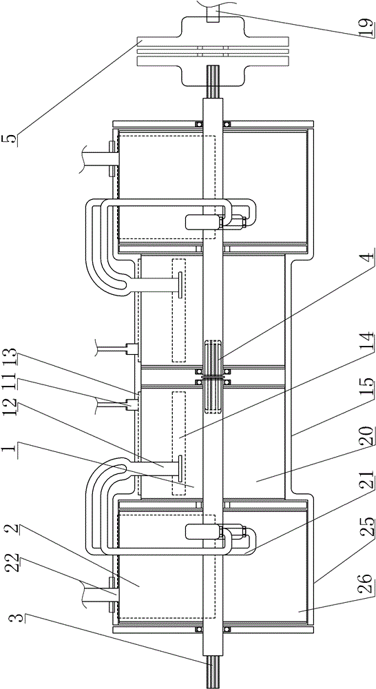
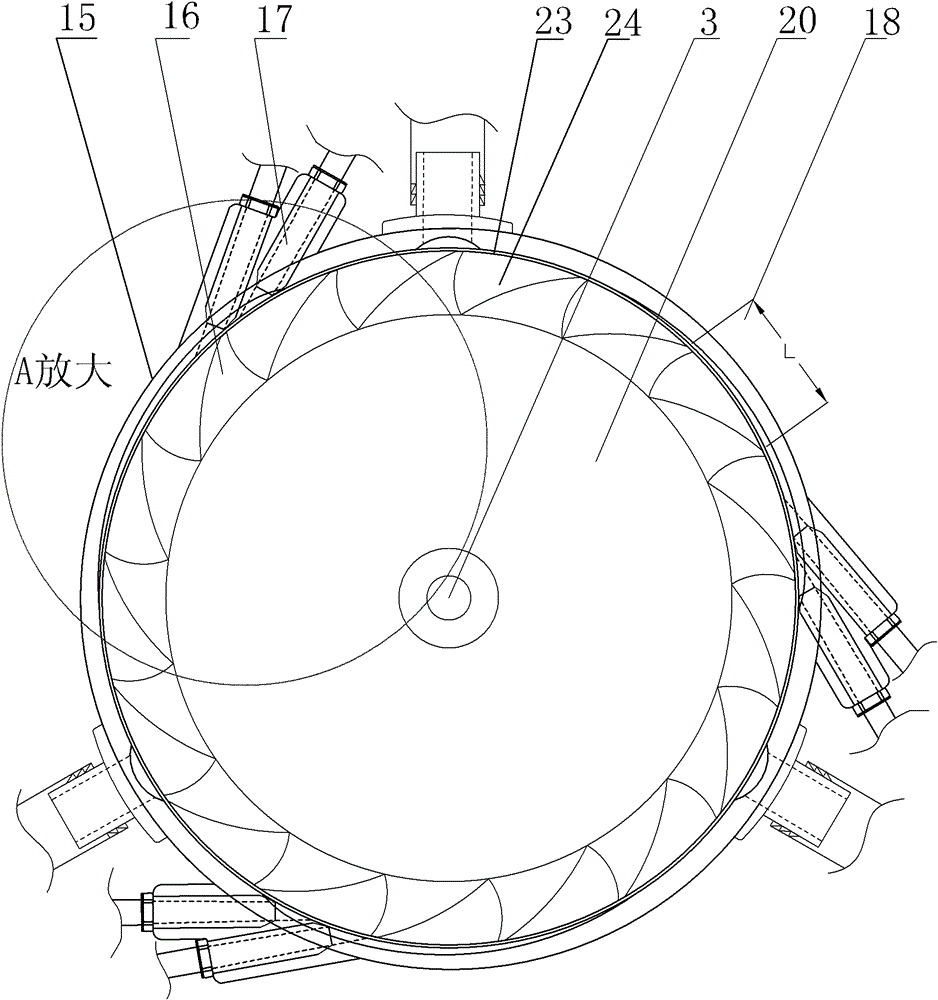
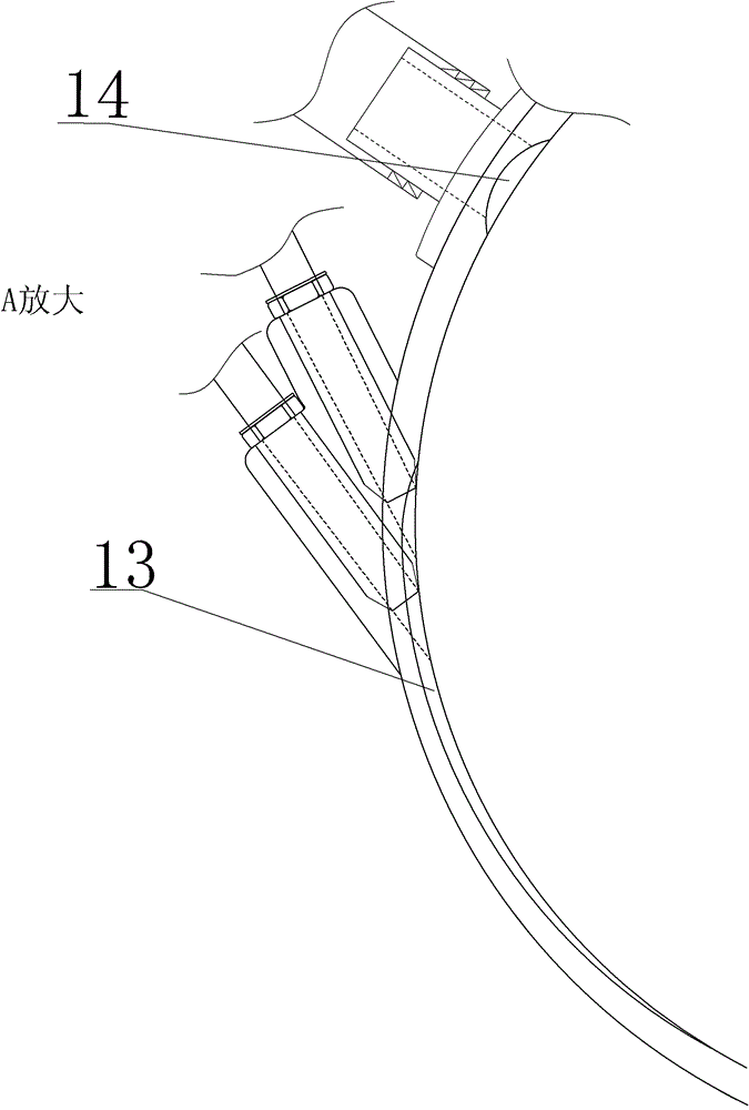
[0034] Embodiment one, a kind of motor vehicle, such as Figure 1 to Figure 3 As shown, it includes a two-stage compressed gas engine and a transmission shaft 19 in a left-right symmetrical structure, wherein the two-stage compressed gas engine on the left side and the two-stage compressed gas engine on the right side have the same structure. Take the two-stage compressed gas engine on the left as an example, including the first-stage compressed gas engine 1 and the second-stage compressed gas engine 2 . The first-stage compressed gas motor 1 includes a first impeller 20 and a first impeller chamber 15, the second-stage compressed gas motor 2 includes a second impeller 26 and a second impeller chamber 25, and the left and right multi-stage compressed gas motors are coaxially installed on the same On the rotating shaft 3, the power generated by the multistage compressed gas engine passes through the rotating shaft 3 and the clutch 5 to transmit the transmission shaft 19 of the ...

Embodiment 2

[0040] Embodiment two, another kind of compressed gas engine, such as Figure 4 Shown, including a two-stage compressed gas engine on the left and a two-stage compressed gas engine on the right. The two-stage compressed gas engine on the left is the first compressed gas engine 100 , and the two-stage compressed gas engine on the right is the second compressed gas engine 200 . The first compressed gas engine 100 and the second compressed gas engine 200 have the same structure and are left-right symmetrical. The first compressed gas motor 100 and the second compressed gas motor 200 are coaxially installed on the rotating shaft 118 and connected through the bearing 108 and the spline sleeve 117 . The power generated by the two-stage compressed gas engines on the left and right sides is output through the rotating shaft 118, and is used to drive the transmission shaft of the motor vehicle.

[0041] Taking the first compressed gas engine 100 as an example, the first compressed ga...

Embodiment 3

[0047] Embodiment three, another kind of multi-stage compressed gas engine, such as Figure 5 Shown, including a two-stage compressed gas engine on the left and a two-stage compressed gas engine on the right. The two-stage compressed gas motor on the left is the first compressed gas motor 300 , and the two-stage compressed gas motor on the right is the second compressed gas motor 400 . The first compressed gas engine 300 and the second compressed gas engine 400 have the same structure and are left-right symmetrical. The first compressed gas motor 100 and the second compressed gas motor 200 are coaxially installed on the rotating shaft 318 and connected through the bearing 308 and the spline sleeve 317 . The power generated by the two-stage compressed gas engines on the left and right sides is output through the rotating shaft 318, and is used to drive the transmission shaft of the motor vehicle.

[0048] Taking the first compressed gas engine 300 as an example, the first com...


PUM


Abstract

The invention discloses a multi-stage compressed gas engine, comprising an impeller and at least one impeller chamber in which the impeller is installed, the impeller includes a first impeller and a second impeller, and blades on the peripheral surfaces of the first impeller and the second impeller The side plates on both sides between the teeth and the blade teeth form a plurality of working chambers, the inner surface of the impeller chamber where the impeller is installed and the working chambers form a plurality of air chambers that can be relatively sealed and injected into the gas, and the first chamber is installed. A first compressed gas injection hole and a first compressed gas discharge hole are correspondingly opened in the impeller chamber of an impeller, and a second compressed gas injection hole and a second compressed gas discharge hole are correspondingly opened in the impeller chamber where the second impeller is installed. and the output of the first compressed gas injection hole is connected to the second compressed gas injection hole. The invention also discloses a motor vehicle equipped with the above-mentioned compressed gas engine. By adopting the present invention, the energy use efficiency of the compressed air can be fully improved.

Description

technical field [0001] The invention relates to an engine, which can be installed on all power machines with running speed, such as large, medium and small passenger and cargo cars, railway trains, subway trains, ship power, aviation power, etc. with steering wheels on land, and belongs to the field of machinery. Background technique [0002] The engine that uses fuel as energy needs to consume a large amount of fuel, and discharges a large amount of exhaust gas and hot gas, polluting the environment. In order to save fuel energy and protect the earth's environment, human beings are more eager for an engine that does not require fuel consumption, eliminates exhaust gas, hot gas emissions, and is pollution-free. [0003] At present, a new energy vehicle powered by compressed gas has gradually appeared. However, there is still a lot of technical work to be done for this new type of new energy vehicle powered by compressed gas. Contents of the invention [0004] The technica...

Claims


Application Information

Patent Timeline
Patent Type & Authority Patents(China)
IPC IPC(8): F01D1/02F01D9/02F01D25/30F01D15/02
Inventor 丛洋
Owner 丛洋
Why Eureka
Try Eureka