Check patentability & draft patents in minutes with Patsnap Eureka AI!

Vehicle lighting device

A technology for lamps and vehicles, applied in the direction of headlights, road vehicles, vehicle parts, etc., to achieve the effect of improving the visibility, improving the appearance, and improving the quality

Inactive Publication Date: 2015-04-01
ICHIKOH IND LTD
View PDF7 Cites 0 Cited by
  • Summary
  • Abstract
  • Description
  • Claims
  • Application Information

AI Technical Summary

Problems solved by technology

Therefore, in conventional vehicle lamps, dark portions, which are non-luminous portions where light from the upper and lower LEDs do not enter, may be formed between the upper and lower light emitting units for lamps.

Method used


Image

  • Vehicle lighting device
  • Vehicle lighting device
  • Vehicle lighting device

Examples


Embodiment 1

[0050] (explanation of structure)

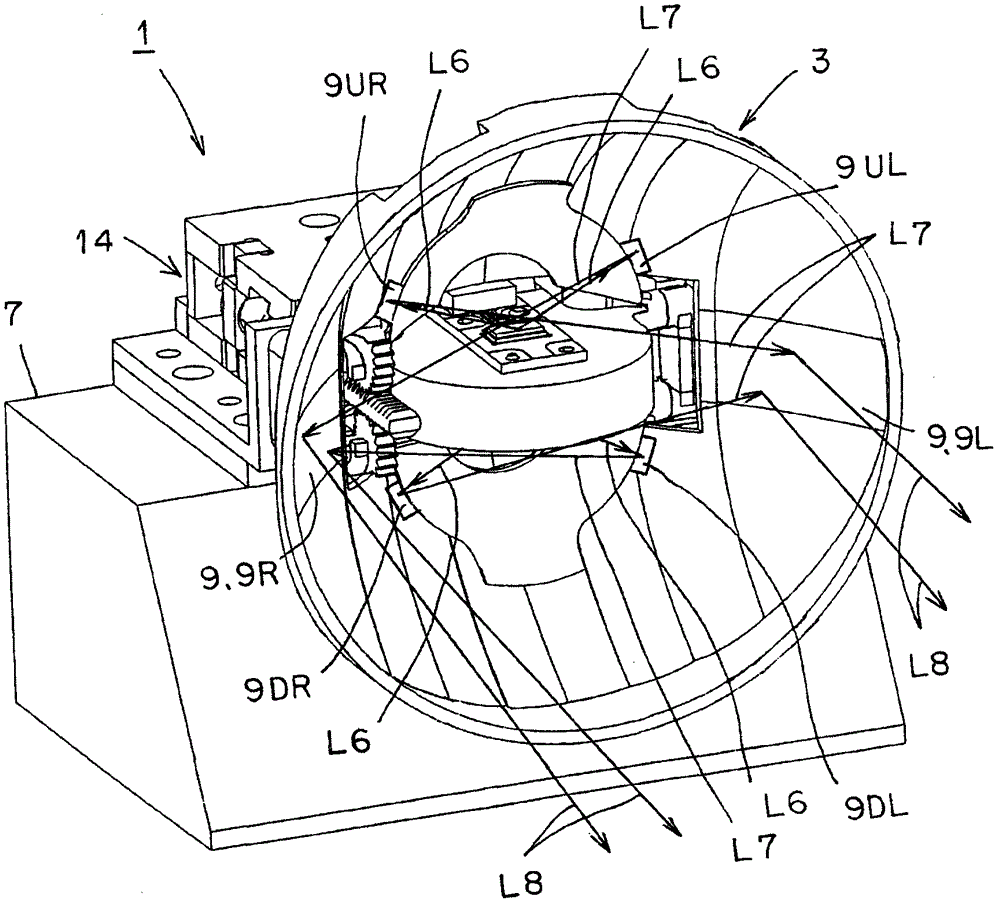
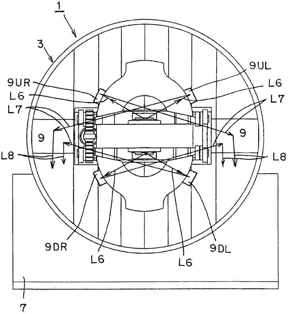
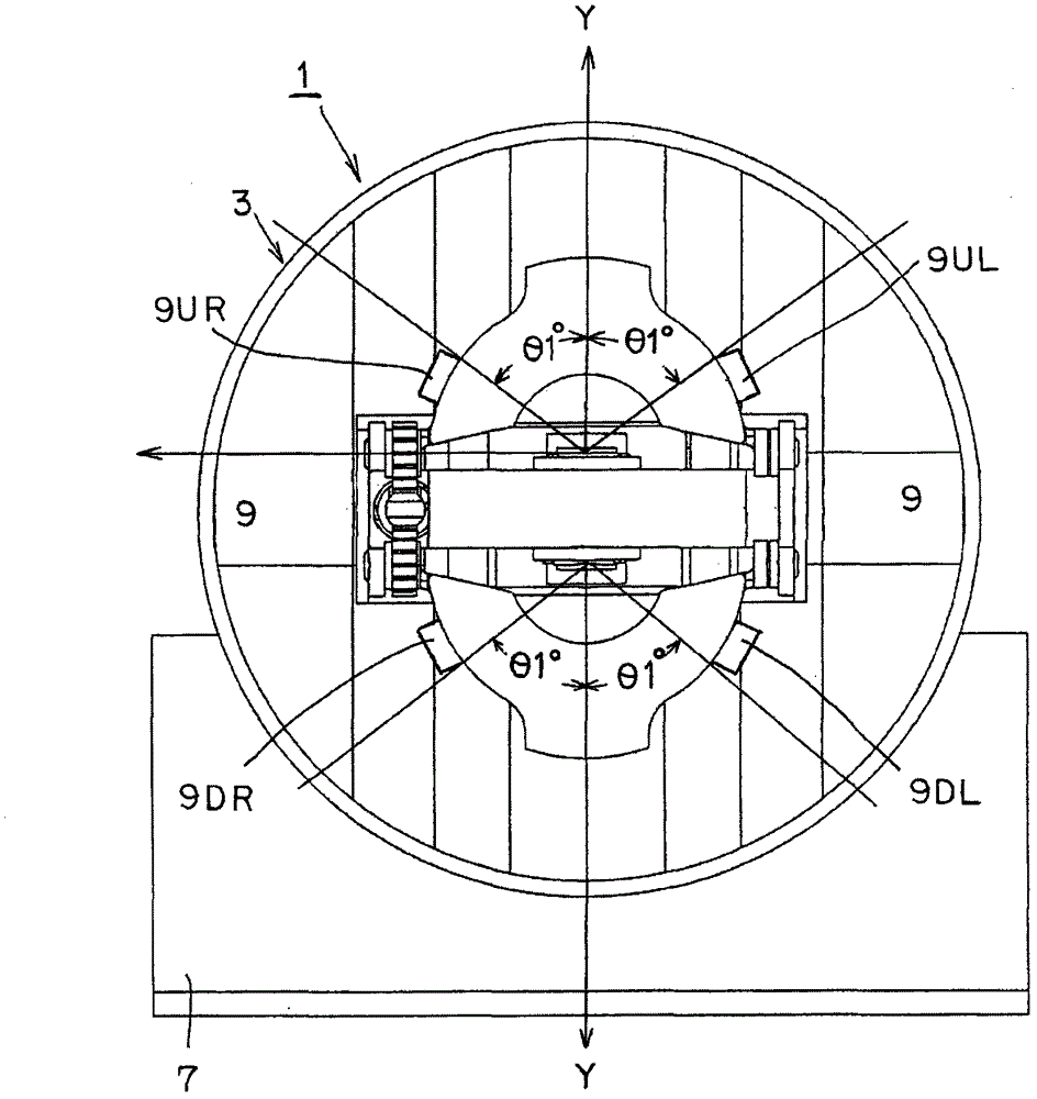
[0051] Figure 1 to Figure 28 Example 1 of the vehicle lamp of the present invention is shown. Hereinafter, the configuration of the vehicle lamp of the first embodiment will be described. In the figure, reference numeral 1 is a vehicle lamp (automobile headlamp) in this embodiment. Conversion of lamps 1 for the above vehicles Figure 27 The low-beam staggered light distribution pattern (the light distribution pattern for staggering, the first light distribution pattern) LP and Figure 28 The shown high beam light distribution pattern (traveling light distribution pattern, second light distribution pattern) is irradiated toward the front of the vehicle.

[0052] The light distribution pattern LP for the above low beam is as Figure 27 As shown, there is an oblique cutoff line CL1 on the traveling lane side (left side) with the inflection point E as a boundary, and a horizontal cutoff line CL2 on the opposite lane side (right side). Als...

Embodiment 2

[0110] (explanation of structure)

[0111] Figure 29 Example 2 of the vehicle lamp of the present invention is shown. Hereinafter, the vehicle lamp in the second embodiment will be described. in the figure, with Figure 1 to Figure 28 The same symbol indicates the same part.

[0112] In the vehicle lamp 1 in the first embodiment described above, when the movable reflectors 13U, 13D are located at the second position, the high beam light distribution patterns HP1, HP2, HP3, LP1 can be obtained. On the other hand, in the vehicular lamp of the second embodiment, when the movable reflectors 13U, 13D are at least in the second position, that is, when the movable reflectors 13U, 13D are in the second position, the configuration for high beam can be obtained as described above. The light patterns HP1, HP2, HP3, LP1, and when the movable reflectors 13U, 13D are located at the third position (the position near the second position) as Figure 29 As shown, the light distribution pa...


PUM


Abstract

According to the present invention, additional reflection surfaces 9UL, 9UR, 9DL, 9DR are provided for reflecting light L6 from semiconductor-type light sources 5U, 5D on intermediate invalid reflection surfaces 9, 9L, 9R. As a result, the present invention is capable of: reflecting the light L6 from the semiconductor-type light sources 5U, 5D on the intermediate invalid reflection surfaces 9, 9L, 9R, by means of the additional reflection surfaces 9UL, 9UR, 9DL, 9DR; illuminating the intermediate invalid reflection surfaces 9, 9L, 9R; and lessening a dark part.

Description

technical field [0001] The present invention relates to a vehicle lamp comprising two light source and reflector units. Background technique [0002] Such a vehicle lamp has been conventionally known (for example, Patent Document 1). A conventional vehicle lamp will be described below. A conventional vehicle lamp is a device in which a light-emitting unit for a lamp is composed of an LED as a light source and a reflective surface that reflects light from the LED in a predetermined light distribution pattern, and two light-emitting units for a lamp are arranged one above the other. The function of the conventional vehicle lamp will be described below. When the upper and lower LEDs are turned on to emit light, the lights from the upper and lower LEDs are respectively reflected by the upper and lower reflective surfaces and irradiated as a predetermined light distribution pattern. [0003] However, conventional vehicle lamps have a structure in which two light-emitting units...

Claims


Application Information

Patent Timeline
Patent Type & Authority Patents(China)
IPC IPC(8): F21S8/12F21V19/00F21V17/00F21V14/04F21V7/06F21W101/02F21Y101/02F21W107/10
CPCF21S48/1323F21S48/1163F21S48/137F21S48/1388F21S48/1757F21S48/1159F21W2101/10F21Y2101/02F21Y2115/10F21S41/321F21S41/336F21S41/36F21S41/675F21W2102/30F21W2102/20F21S45/48F21W2102/155F21S41/148F21W2102/00
Inventor 岩崎和则杉江良裕
Owner ICHIKOH IND LTD
Features
  • R&D
  • Intellectual Property
  • Life Sciences
  • Materials
  • Tech Scout
  • Unparalleled Data Quality
  • Higher Quality Content
  • 60% Fewer Hallucinations
Learn More