Light guiding plate
A light guide plate and reflective surface technology, applied in the field of light guide plates, can solve problems such as poor brightness uniformity, achieve the effects of eliminating shadows, easy control of exit angles, and improvement of light energy utilization
- Summary
- Abstract
- Description
- Claims
- Application Information
AI Technical Summary
Problems solved by technology
Method used
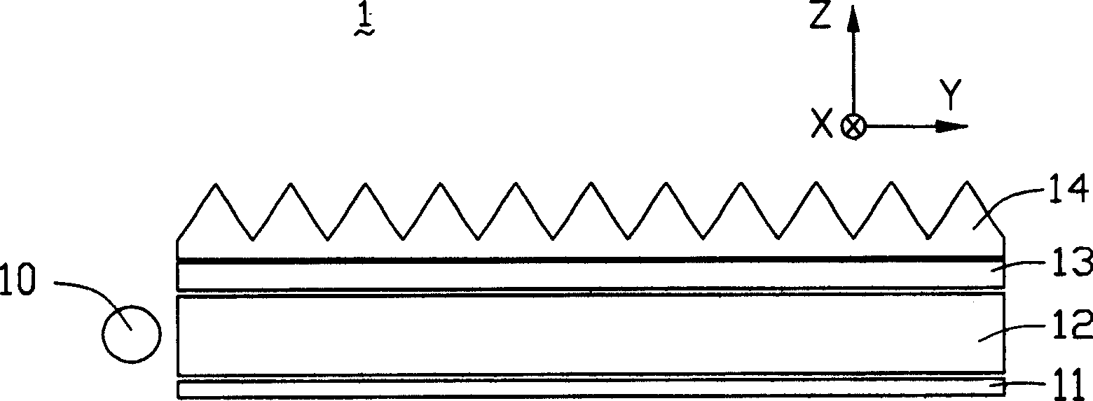
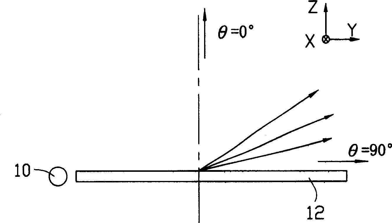
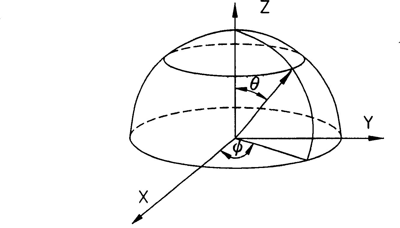
Image

Examples
Embodiment Construction
[0041] The structure of the light guide plate of the present invention will be further described in detail with reference to the drawings and multiple embodiments.
[0042] Such as Figure 6As shown, the light guide plate 60 of the first embodiment has an incident surface 61 (a side surface), a reflective surface 62 (lower surface) and an outgoing surface 64 (upper surface); The V-shaped structure 644 forms a plurality of second V-shaped structures 622 on the surface of the reflecting surface 62 , and the directions of the second V-shaped structures 622 on the reflecting surface and the first V-shaped structures 644 on the emitting surface are perpendicular to each other.
[0043] The light guide plate 60 is a flat plate structure, which can be made of polycarbonate (PC), polymethyl methacrylate (PMMA), or acrylic and other common light guide plate materials and synthetic resin materials.
[0044] Such as Figure 7 As shown, the plurality of first V-shaped structures 644 for...
PUM
| Property | Measurement | Unit |
|---|---|---|
| height | aaaaa | aaaaa |
| angle | aaaaa | aaaaa |
| width | aaaaa | aaaaa |
Abstract
Description
Claims
Application Information
 - R&D
- Intellectual Property
- Life Sciences
- Materials
- Tech Scout
- Unparalleled Data Quality
- Higher Quality Content
- 60% Fewer Hallucinations
Browse by: Latest US Patents, China's latest patents, Technical Efficacy Thesaurus, Application Domain, Technology Topic, Popular Technical Reports.
© 2025 PatSnap. All rights reserved.Legal|Privacy policy|Modern Slavery Act Transparency Statement|Sitemap|About US| Contact US: help@patsnap.com