Motor stator structure for flux weakening speed regulation
What is AI technical title?
AI technical title is built by Patsnap AI team. It summarizes the technical point description of the patent document.
A stator structure, weak field speed regulation technology, applied in the direction of the shape/style/structure of the magnetic circuit, the static parts of the magnetic circuit, etc., can solve the problem of difficult weak field control
Inactive Publication Date: 2013-02-27
BEIJING JIAOTONG UNIV
View PDF4 Cites 0 Cited by
Summary
Abstract
Description
Claims
Application Information
AI Technical Summary
This helps you quickly interpret patents by identifying the three key elements:
Problems solved by technology
Method used
Benefits of technology
Problems solved by technology
[0003] The technical problem to be solved by the present invention is to overcome the problem that the existing motor structure is difficult to realize the field weakening control, and to provide a motor stator structure
Method used
Image
Click on the blue label to locate the original text in one second.
Reading with bidirectional positioning of images and text.
Examples
Embodiment approach 1
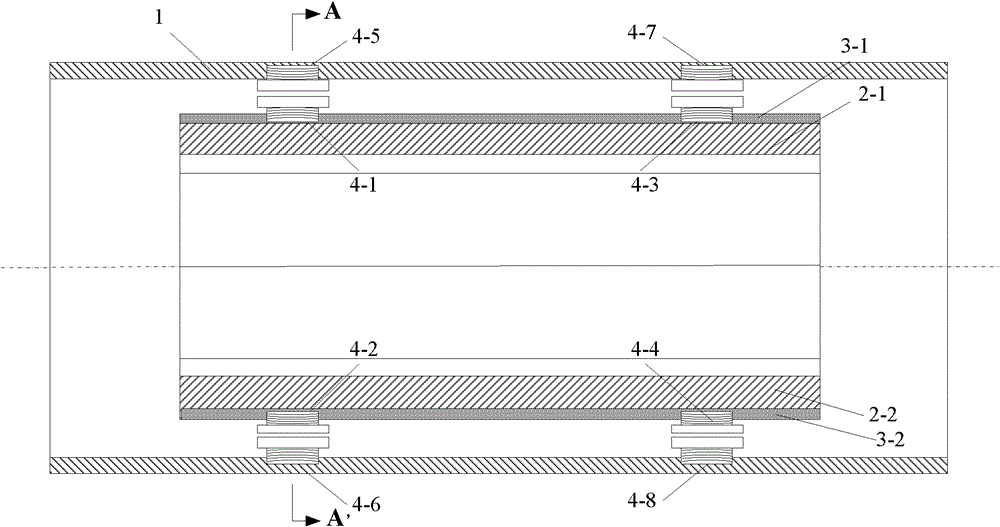
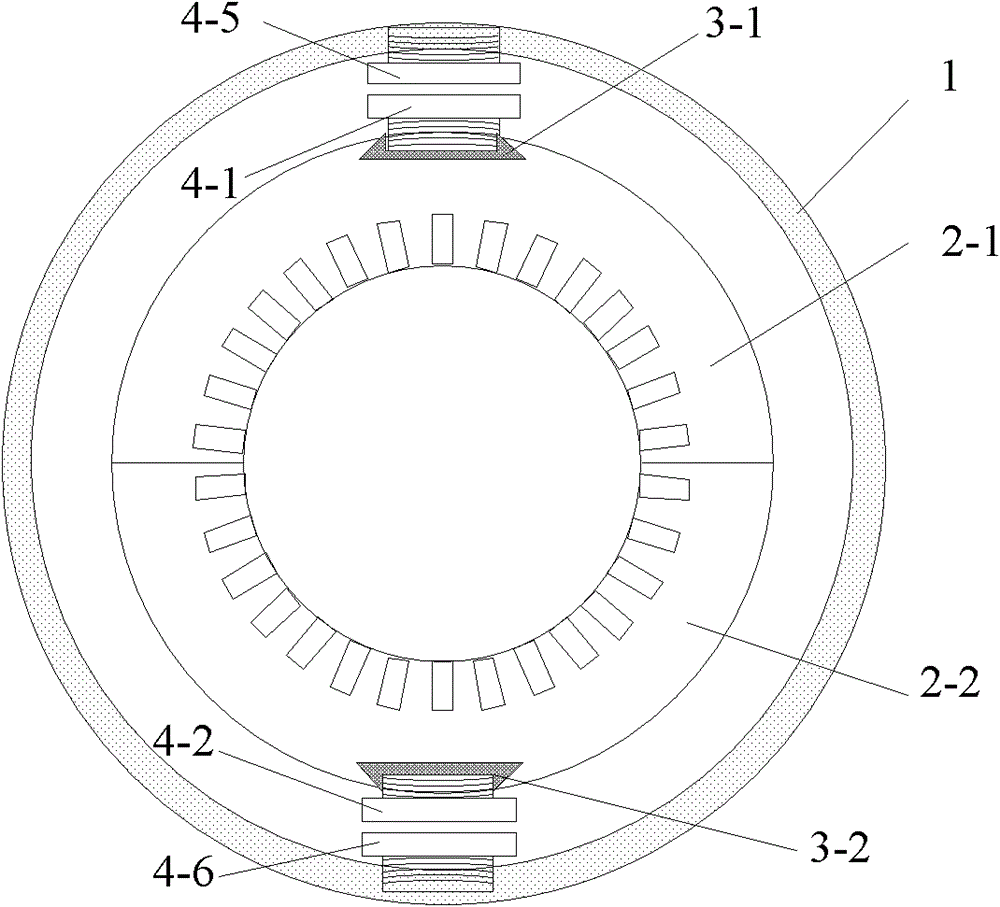
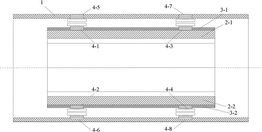
[0033] A stator structure for motor field-weakening speed regulation, the stator structure includes a casing 1, a stator core, such as figure 1 , 2 shown. The stator core includes an upper split stator core 2-1 and a lower split stator core 2-2.
[0034] A dovetail groove is axially arranged on the top of the upper split stator core 2-1, and a first magnetic isolation plate 3-1 is installed in the dovetail groove, and a first magnetic isolation plate 3-1 is installed in the axial direction in the first magnetic isolation plate 3-1. Iron 4-1 and the third electromagnet 4-3.
[0035] A dovetail slot is axially arranged at the bottom of the lower split stator core 2-2, a second magnetic isolation plate 3-2 is installed in the dovetail slot, and a second electromagnet is installed axially in the second magnetic isolation plate 3-2 4-2 and the fourth electromagnet 4-4.
[0036] On the position corresponding to the first electromagnet 4-1 and the third electromagnet 4-3 installe...
Embodiment approach 2
[0046] The difference between Embodiment 2 and Embodiment 1:
[0047] There are first and second tension springs 5-1, 5-2 and third and fourth tension springs 5-3 and 5-4 between the casing 1 and the upper split stator core 2-1; The first and second pressure springs 6-1 and 6-2 and the third and fourth pressure springs 6-3 and 6-4 are arranged between the casing 1 and the lower split stator core 2-2.
[0048] The first and second tension springs 5-1, 5-2 and the first and second pressure springs 6-1, 6-2 are in the same axial cross-section and evenly distributed along the circumference.
[0049] The third and fourth tension springs 5-3 and 5-4 and the third and fourth pressure springs 6-3 and 6-4 are in the same axial cross-section and evenly distributed along the circumference. Such as image 3 , 4 , 5, and 6.
Embodiment approach 3
[0051] The difference between Embodiment 3 and Embodiment 1:
[0052] Described first electromagnet 4-1, the second electromagnet 4-2 and the 3rd electromagnet 4-3, the 4th electromagnet 4-4 respectively use the first permanent magnet 7-1, the second permanent magnet 7-2 , the third permanent magnet 7-3 and the fourth permanent magnet 7-4 instead, as Figure 7 , 8 shown.
PUM
Abstract
A motor stator structure for flux weakening speed regulation belongs to the field of motors. The invention solves the technical problem that a current motor structure is difficult in realizing flux weakening control, and provides a motor stator structure. The invention proposes an upper split stator iron core and a lower split stator iron core; the middle of each of the upper and lower split stator iron cores is provided with a dovetail along the axial direction, and a magnetism separating plate is equipped in each dovetail; a casing and the magnetism separating plate of each of the upper and lower split stator iron cores are respectively provided with two groups of electromagnets in the axial directions; when flux weakening control is carried out, the upper electromagnets are electrified, forming mutually attracting electromagnetic forces to drive the upper split stator iron core to move towards the casing, the electrifying current of the lower electromagnet is decreases, the repulsion forces are reduced, and the lower split stator iron core also moves towards the casing, such that the split stator iron core is divided into two parts. By adjusting the radial and tangential air magnetic resistances in an electromagnetic main magnetic circuit, the magnetic voltage drop allocation and the main magnetic flux are changed, thus realizing the flux weakening control of a motor; and the structure is simple and easy to realize.
Description
technical field [0001] The invention relates to a motor stator structure capable of realizing field-weakening control, belonging to the field of motors. Background technique [0002] As more and more advanced production and processing equipment are designed and put into operation, the requirements for their drive and execution units continue to increase. Therefore, the motor is required to run smoothly at a wider range of speeds. In order to make the motor run stably when the speed is higher than the rated speed, the control method of weakening the main pole magnetic flux Φ is generally adopted. However, it is difficult to achieve field-weakening control for some motors. For example, permanent magnet synchronous motors are excited by permanent magnets, and the excitation strength of the permanent magnets cannot be adjusted; The output voltage is the rated voltage of the motor, and the motor current increases to exceed the rated value. These will affect the operating effici...
Claims
Application Information
Patent Timeline
Application Date:The date an application was filed.
Publication Date:The date a patent or application was officially published.
First Publication Date:The earliest publication date of a patent with the same application number.
Issue Date:Publication date of the patent grant document.
PCT Entry Date:The Entry date of PCT National Phase.
Estimated Expiry Date:The statutory expiry date of a patent right according to the Patent Law, and it is the longest term of protection that the patent right can achieve without the termination of the patent right due to other reasons(Term extension factor has been taken into account ).
Invalid Date:Actual expiry date is based on effective date or publication date of legal transaction data of invalid patent.

