A Synchronous Motor Excitation System

A synchronous motor and excitation system technology, applied in the field of excitation system, can solve the problems of insufficient excitation of the motor, insufficient output torque of the motor, and excessive excitation voltage.

Active Publication Date: 2021-10-22
HARBIN INST OF TECH
View PDF6 Cites 0 Cited by
  • Summary
  • Abstract
  • Description
  • Claims
  • Application Information

AI Technical Summary

Problems solved by technology

Therefore, the excitation voltage increases with the increase of the motor speed, so this structure can only be used in fields such as generators with relatively fixed speed and relatively simple working conditions
However, in the working area where the motor speed is low, due to insufficient motor speed, the excitation voltage drops, and the motor cannot be fully excited, resulting in insufficient motor output torque.
In the high-speed region, the excitation voltage is too high, resulting in over-excitation of the motor and increased loss

Method used


Image

  • A Synchronous Motor Excitation System
  • A Synchronous Motor Excitation System
  • A Synchronous Motor Excitation System

Examples


specific Embodiment approach 1

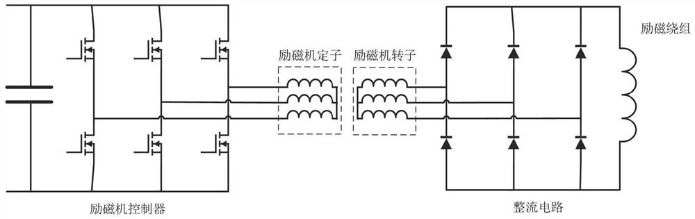
[0022] Combine below Figures 1 to 6 Description of this embodiment, a synchronous motor excitation system, including a controller and an exciter, the exciter and the synchronous motor are coaxially connected, and the controller adjusts the three-phase voltage input to the exciter; The frequency and amplitude of the excitation voltage can be flexibly controlled through the controller, which can be adapted to the rotor of the synchronous motor to the greatest extent, so that the synchronous motor can be excited in the full speed range, and the synchronous motor can be guaranteed at low speeds. Torque output, and realize the field weakening control of the synchronous motor rotor in the high speed section.

specific Embodiment approach 2

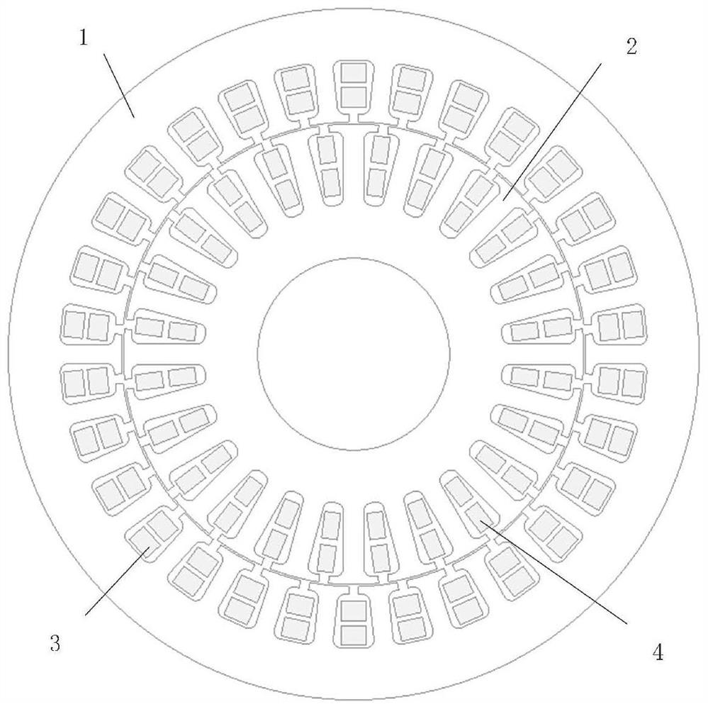
[0023] Combine below Figures 1 to 6 Describe this embodiment, this embodiment will further explain the first embodiment, the exciter includes the exciter stator core 1, the exciter rotor core 2, the exciter stator winding 3 and the exciter rotor winding 4, the exciter stator iron core The exciter stator winding 3 is arranged on the core 1, the exciter rotor winding 4 is arranged on the exciter rotor iron core 2, the exciter rotor iron core 2 and the synchronous motor are connected coaxially through the shaft 11, the exciter stator winding 3 and the exciter Air gaps are provided between the rotor windings 4 .

specific Embodiment approach 3

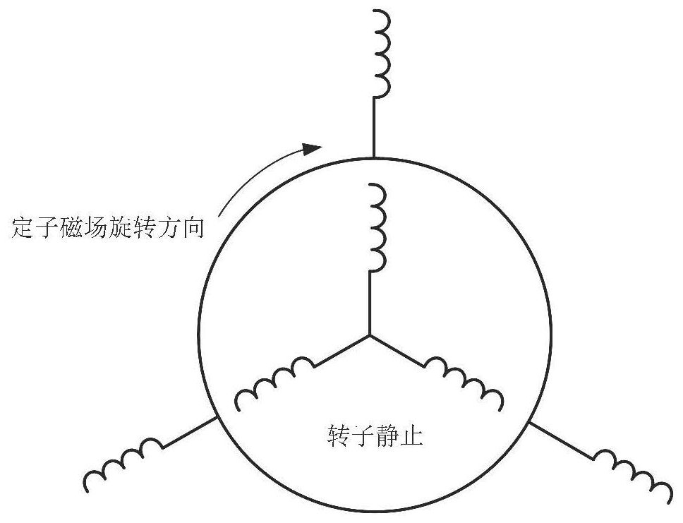
[0024] Combine below Figures 1 to 6 This embodiment will be described. This embodiment will further describe the second embodiment. The stator winding 3 of the exciter is a symmetrical three-phase excitation winding, and the three-phase voltage is passed into the stator winding 3 of the exciter.


PUM


Abstract

The present invention relates to an excitation system, more specifically an excitation system for a synchronous motor, including a controller and an exciter, the exciter and the synchronous motor are coaxially connected, the controller adjusts the three-phase voltage input to the exciter, and the exciter includes The exciter stator core, the exciter rotor core, the exciter stator winding and the exciter rotor winding, the exciter stator core is provided with the exciter stator winding, the exciter rotor core is provided with the exciter rotor winding, the exciter The rotor core and the synchronous motor are coaxially connected through the shaft, and there is an air gap between the exciter stator winding and the exciter rotor winding, and the excitation voltage can be flexibly controlled by the controller by feeding three-phase or DC power into the exciter The frequency and amplitude can be adapted to the rotor of the synchronous motor to the greatest extent, so that the synchronous motor can be excited in the full speed range, the torque output of the synchronous motor can be guaranteed in the low speed section, and the magnetic field weakening of the synchronous motor rotor can be realized in the high speed section control.

Description

technical field [0001] The invention relates to an excitation system, in particular to an excitation system of a synchronous motor. Background technique [0002] Synchronous motors have the advantages of high efficiency and adjustable magnetic field, and have great application prospects in the field of new energy vehicles, but they require carbon brush components, which reduces the reliability of the motor. The excitation voltage of the traditional motor brushless excitation system changes with the speed, and it cannot maintain stable excitation when the motor speed changes. [0003] The structure of the traditional synchronous motor brushless excitation system is similar to that of a DC motor. There are fixed coils in the stator of the excitation system to generate a magnetic field. The rotor coil of the excitation system cuts the magnetic field lines of this magnetic field when it rotates, and it will be at the output port of the rotor. The AC induced voltage is generated...

Claims


Application Information

Patent Timeline
Patent Type & Authority Patents(China)
IPC IPC(8): H02P6/32H02P6/08
CPCH02P6/08H02P6/32
Inventor 杜博超吴绍朋崔淑梅
Owner HARBIN INST OF TECH
Why Eureka
Try Eureka