
Magnetic isolation driving circuit

A technology of isolated drive and drive circuit, which is applied in the direction of electrical components, output power conversion devices, etc., and can solve problems such as large drive signals and inability to transmit duty cycles

Active Publication Date: 2013-05-15
BEIJING SUPLET +1
View PDF6 Cites 0 Cited by
  • Summary
  • Abstract
  • Description
  • Claims
  • Application Information

AI Technical Summary

Problems solved by technology

[0003] In view of this, the present invention provides a magnetically isolated driving circuit to overcome the problems in the prior art that cannot transmit driving signals with a large duty cycle and misleading circuit failure due to the series connection of DC blocking capacitors in the driving transformer

Method used


Image

  • Magnetic isolation driving circuit
  • Magnetic isolation driving circuit

Examples


Embodiment Construction

[0011] In order to make the purpose, technical solutions and advantages of the embodiments of the present invention clearer, the technical solutions in the embodiments of the present invention will be clearly and completely described below in conjunction with the drawings in the embodiments of the present invention. Obviously, the described embodiments It is a part of embodiments of the present invention, but not all embodiments. Based on the embodiments of the present invention, all other embodiments obtained by persons of ordinary skill in the art without making creative efforts belong to the protection scope of the present invention.

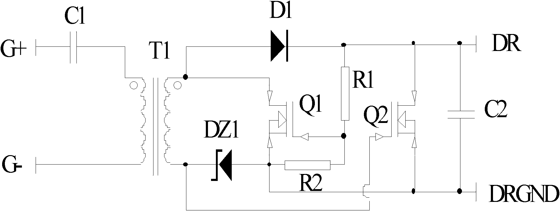
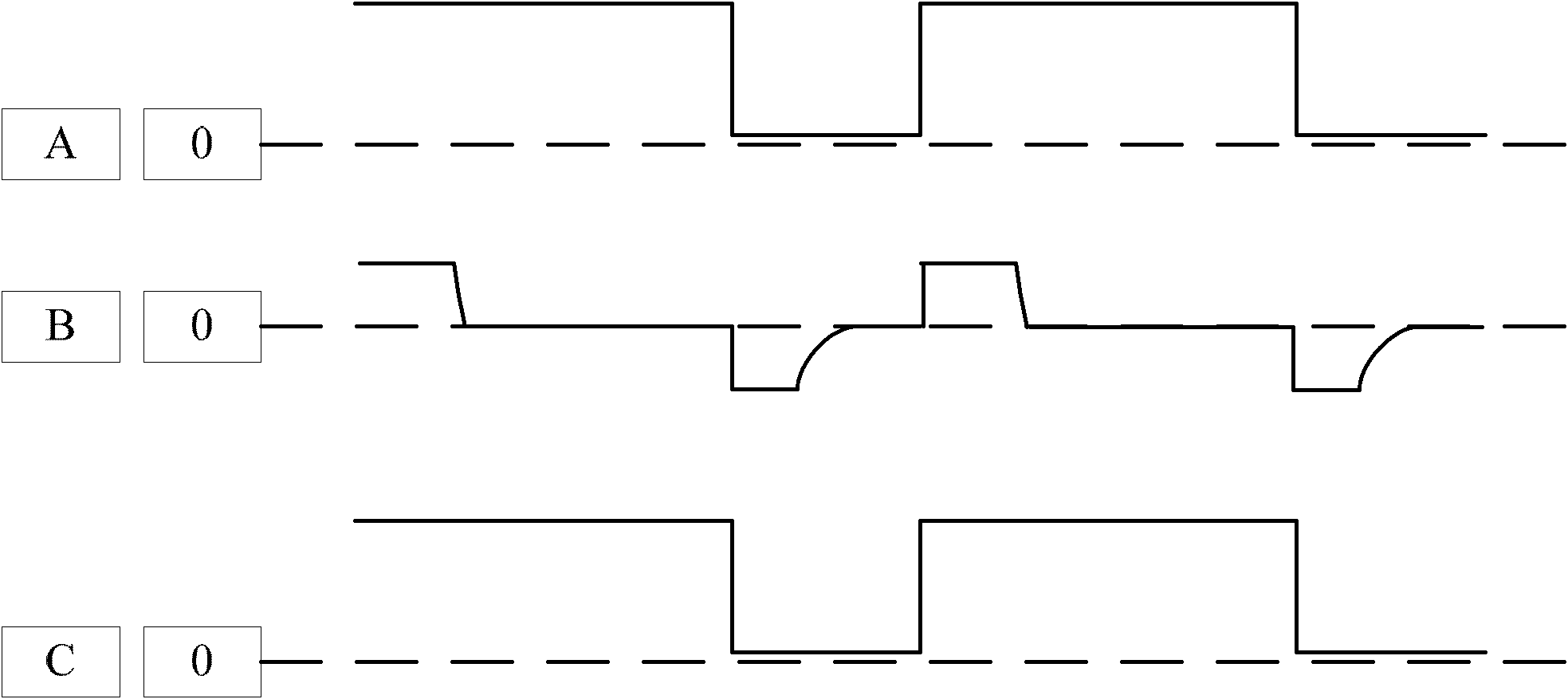
[0012] figure 1 A schematic diagram of a magnetic isolation driving circuit provided by the present invention is shown, the magnetic isolation driving circuit includes an isolation driving transformer T1, a primary winding, a first capacitor C1, a secondary winding, a first switching tube Q1, a voltage regulator tube DZ1, diode D1, second sw...


PUM


Abstract

The invention provides a magnetic isolation driving circuit which comprises an isolation driving transformer T1, an original vice-side winding, a first capacitor C1, a first switch tube Q1, a voltage stabilizing tube DZ1, a diode D1, a second switch tube Q2, a second capacitor C2, a first resistor R1 and a second resistor R2. The magnetic isolation driving circuit is applicable to various duty ratio signal circuits and circuits requiring complex drive control.

Description

technical field [0001] The invention belongs to the field of DC / DC power supply circuits, in particular to a magnetic isolation drive circuit. Background technique [0002] At present, in the field of switching power supplies, isolated drive technology is widely used, and a large number of bridge circuits and synchronous rectification circuits use isolated drive technology. Isolation drive technology usually uses isolation drive transformers and peripheral circuits to transmit high-speed drive signals. In the process of driving signal transmission, in order to prevent the saturation of the isolation drive transformer, a DC blocking capacitor with a larger capacitance is usually connected in series with the primary winding and the secondary winding of the isolation drive transformer. However, the DC blocking capacitor will divide the signals at both ends of the primary and secondary windings of the driving transformer into positive and negative parts, and the change of the d...

Claims


Application Information

Patent Timeline
Patent Type & Authority Patents(China)
IPC IPC(8): H02M1/08
Inventor 蔡宇翔金祖敏
Owner BEIJING SUPLET
Learn More