A cold bending equipment and method for manufacturing U-shaped bar

A U-shaped, cold-state technology, which is applied in the field of cold-state bending equipment for manufacturing U-shaped rods, can solve the problems of metal material structure changes, low bending control precision, and unsuitable use in occasions with high material performance requirements, and achieves guaranteed The effect of precision

Active Publication Date: 2011-12-21
CHINA NUCLEAR POWER ENG CO LTD +1
View PDF3 Cites 15 Cited by
  • Summary
  • Abstract
  • Description
  • Claims
  • Application Information

AI Technical Summary

Problems solved by technology

[0003] Most of the existing U-shaped bar manufacturing processes use heating and bending. Although metal materials are easier to bend and deform after heating, the heating process will cause changes in the internal structure of the metal material, which is not suitable for occasions wit

Method used


Image

  • A cold bending equipment and method for manufacturing U-shaped bar
  • A cold bending equipment and method for manufacturing U-shaped bar
  • A cold bending equipment and method for manufacturing U-shaped bar

Examples


Embodiment

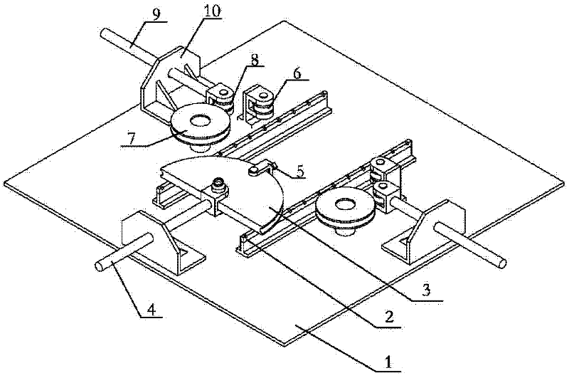
[0030]A steel bar with a diameter of 30mm is provided below, and the U section is bent into a semicircle with a radius of 363mm. An embodiment of the cold bending equipment for manufacturing U-shaped rods.

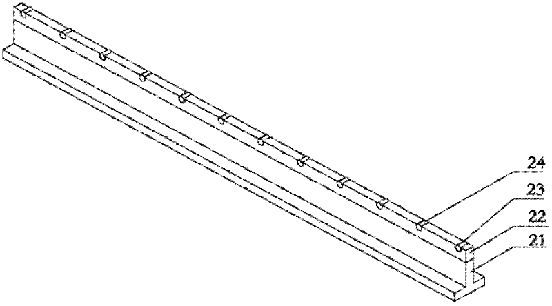
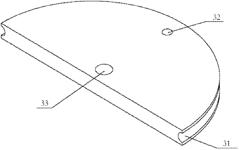
[0031] The distance between two parallel guide rails is 500mm, and the width of the guide rails is 20mm. On the guide rails, rollers with a diameter of 10mm are equidistant at 100mm intervals; the mold is pushed forward to a semicircle with a radius of 363mm and a thickness of 50mm. For a groove with a radius of 16mm, the center of the groove on the cross section is 1mm away from the arc edge of the positively pushing mold, that is, the depth of the groove on the forwardly pushing mold is 15mm. The grooves of pads in other lateral guide pulleys, lateral push pulleys and steel bar fixtures are also provided with the same. The diameter of the small lateral guide pulleys on both sides is 100mm, and the diameter of the large lateral guide pulleys is 300mm. The distance between...


PUM


Abstract

The invention relates to the field of machinery manufacturing, in particular to cold bending equipment and a method for manufacturing a U-shaped rod. The cold bending equipment for manufacturing the U-shaped rod structurally comprises a guide rail device which is fixed on a bottom plate; a positive push mould capable of freely moving along the direction of a guide rail is arranged on the guide rail device; the front part of the positive push mould is in a circular arc shape; a groove is arranged on the outer edge of the circular arc shape; a driving rod is arranged on the positive push mould; the driving rod passes through a driving rod base and is connected with a driving device; sideward guiding pulley devices are symmetrically arranged on both sides of the guide rail device; sideward push pulleys capable of freely moving along the direction which is vertical to the guide rail are respectively arranged on both sides of the guide rail device; the driving rods are arranged on the sideward push pulleys, pass through the driving rod bases and are connected with the driving device; and the positive push mould, the sideward guiding pulley devices and the sideward push pulleys are arranged on the same plane. The invention can realize the once-through cold formation of the U-shaped rod, so that no danger occurs in a bending process, and the resilience problem of the U-shaped rod can be solved.

Description

technical field [0001] The invention relates to the field of mechanical manufacturing, in particular to a cold bending equipment and method for manufacturing U-shaped bars. Background technique [0002] Many pipe supports in engineering construction need to use U-shaped pipe clips. U-shaped pipe clips are made of bent steel rods. Because most of the U-shaped pipe clips used in supports do not require high precision, many can be used. method for bending. In the process of developing the U-shaped anti-shock limiter for nuclear power plants, strict precision requirements are put forward for the radius of the semicircular part of the U-shaped rod, and the material properties of the arc part and the straight part during the bending process are required. Rather, since the material of the steel bar is stainless steel, it is not desirable to use heating to change the internal grains of the material, and it is required to use cold bending. During the bending process, no large stres...

Claims


Application Information

Patent Timeline
IPC IPC(8): B21D7/04
Inventor 王付军杨世宽刘伟高金刚于勇王宏杰郑杰刘虎崔昊盛锋王应东
Owner CHINA NUCLEAR POWER ENG CO LTD
Why Eureka
Try Eureka