
One-time forming mold for steel cap of pin type insulator

A technology of pin-type insulators and forming molds, applied in forming tools, manufacturing tools, metal processing equipment, etc., can solve the problems of low yield, unforged holes in tube crimping parts, hidden dangers, etc., and achieve high yield , good effect of punching

Inactive Publication Date: 2011-12-21
RUGAO DASHENG LINE EQUIP
View PDF5 Cites 10 Cited by
  • Summary
  • Abstract
  • Description
  • Claims
  • Application Information

AI Technical Summary

Problems solved by technology

At present, there are two ways to produce this kind of pin-type insulator steel cap: one is to adopt the method of casting to shape, and its disadvantages are: the internal structure is loose, there are defects such as shrinkage cavities and cracks, the quality cannot meet the requirements, and there are large potential safety hazards, and more scrapped
The disadvantages of this kind are: the crimping part of the forged steel cap is prone to insufficient punching, resulting in the scrapping of the product, high energy consumption, low yield, and the hole of the tube crimping part cannot be forged, so it must be machined can only be made, and the manufacturing cost is very high

Method used


Image

  • One-time forming mold for steel cap of pin type insulator
  • One-time forming mold for steel cap of pin type insulator
  • One-time forming mold for steel cap of pin type insulator

Examples


Embodiment Construction

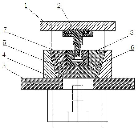
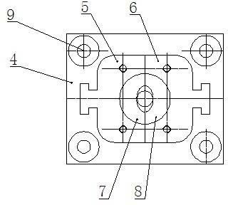
[0010] Such as figure 1 , 2 As shown, it includes an upper template 1, a punch 2, a lower template 3, a mold base 4, a left mold 5, a right mold 6, a guide hole 9, a left mold core 7 and a right mold core 8.

[0011] On the above-mentioned upper template 1, a punch 2 is installed through a fixed plate, and a mold base 4 is provided on the lower template 3, and a left mold 5 and a right mold 6 are symmetrically arranged in the mold base 4, and the left mold 5 and the right mold 6 are provided with a T-shaped slider structure, the mold base 4 is provided with a T-shaped guide groove that can be fitted with a T-shaped slider, and the T-shaped guide groove extends obliquely upward from the bottom of the mold base.

[0012] The four corners of the upper formwork 1 are provided with guide posts, and the four corners of the mold base 4 are provided with guide holes 9 corresponding to the guide posts.

[0013] The inner surfaces of the left mold 5 and the right mold 6 are respective...


PUM


Abstract

The invention relates to a one-time forming mold for a pin-type insulator steel cap, which includes an upper template and a lower template. The left mold and the right mold, the outside of the left mold and the right mold are provided with a T-shaped slider structure, the mold base is provided with a T-shaped guide groove that can fit the T-shaped slider, and the T-shaped guide groove is formed from the bottom of the mold base The outside extends obliquely upwards; the inner surfaces of the left mold and the right mold are respectively connected with a left mold core and a right mold core by bolts, and the combination of the left mold core and the right mold core forms a cavity of a pin-type insulator steel cap. Through the cooperation of the punch and the left and right mold cores, the pin-type insulator steel cap is punched and formed at one time, and the punching effect is good and the yield is high. When demoulding, the left and right molds are lifted by the demoulding cylinder below, so that the left and right molds are opened to both sides under the action of the T-shaped slider and the T-shaped guide groove, and the demoulding of the steel cap is realized.

Description

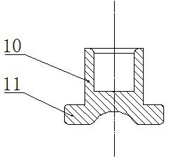
technical field [0001] The invention relates to a mold, in particular to a one-time forming mold for a pin-type insulator steel cap. Background technique [0002] Pin insulator steel caps are used for the connection between tower poles and wires below 20KV in rural power grids and urban power grids, such as figure 1 As shown, it consists of a tubular crimping portion 10 and a seat portion 11 . At present, there are two ways to produce this kind of pin insulator steel cap: one is to adopt the method of casting to form, and its disadvantages are: the internal structure is loose, there are defects such as shrinkage cavities and cracks, the quality cannot meet the requirements, and there are large potential safety hazards, and more scrapped. [0003] The method of forging can also be adopted, and the inner cavity of the mold is the cavity of the pin-type insulator steel cap. In order to realize unloading, the crimping part of the steel cap is on the bottom, and the support par...

Claims


Application Information

Patent Timeline
Patent Type & Authority Applications(China)
IPC IPC(8): B21D37/10B21D45/04
Inventor 征大生刘松明
Owner RUGAO DASHENG LINE EQUIP
Learn More