
Printer automatic paper cutter structure

A paper cutter and printer technology, applied in printing devices, printing, etc., can solve problems affecting performance, paper cutting, and limited cutting life

Active Publication Date: 2011-12-21
XIAMEN HANIN ELECTRONICS TECH CO LTD
View PDF5 Cites 3 Cited by
  • Summary
  • Abstract
  • Description
  • Claims
  • Application Information

AI Technical Summary

Problems solved by technology

[0005] 1. The paper cannot be cut when the paper is fully cut, which affects the performance;
[0006] 2. The cutting life is limited, and the paper cutting is not smooth enough
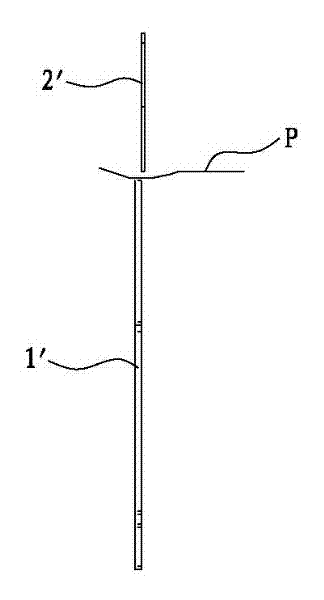
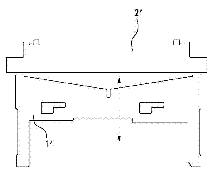
[0007] The reason for the above two problems is that during the paper cutting process, the stress of the upper cutting blade 1' and the lower cutting blade 2' when they are cut is all squeezed to the middle of each cutting blade, causing great resistance, especially The lower cutting blade 2' whose cutting edge 21' is in a straight line will have greater resistance; if there is a slight deviation in the left and right elastic control of each cutting blade, it will affect each other, so that the paper cannot be cut

Method used


Image

  • Printer automatic paper cutter structure
  • Printer automatic paper cutter structure
  • Printer automatic paper cutter structure

Examples


Embodiment Construction

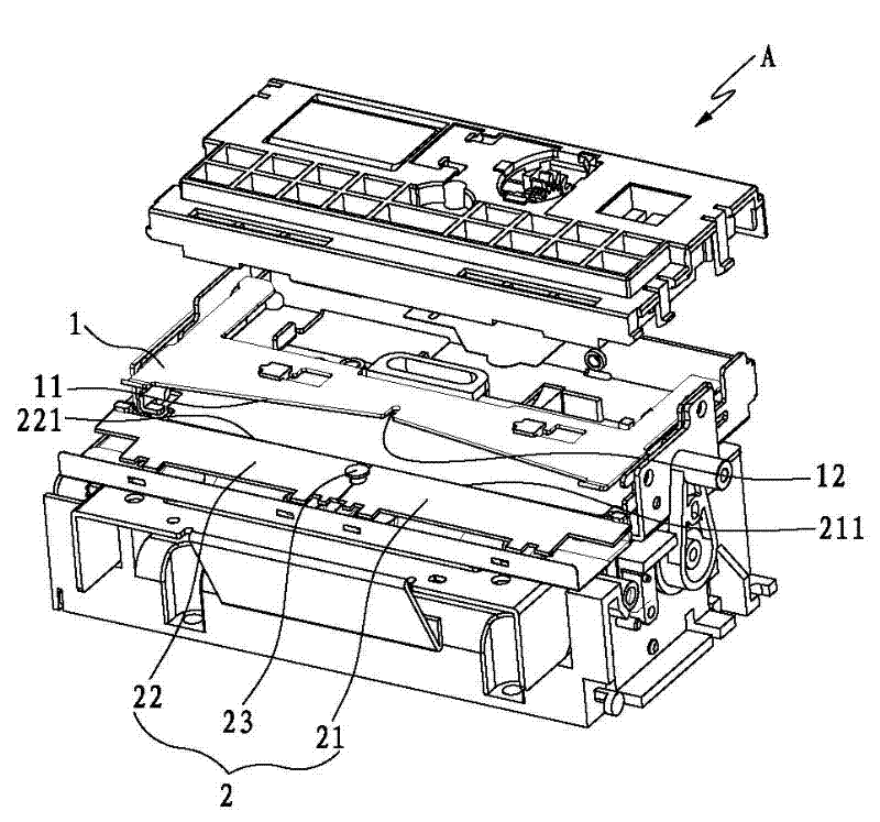
[0022] like Figure 3 to Figure 9 As shown, the present invention discloses a printer automatic paper cutter structure, which is arranged at the paper outlet of the printing module A of the printer, which includes an upper cutting blade 1 located above the paper outlet and a lower blade 1 located below the paper outlet. Cutting blade 2, the upper and lower cutting blades are relatively movable; the key of the present invention is:

[0023] The lower cutting blade 2 is composed of a lower left cutting blade 21 and a lower right cutting blade 22, and the butt joint between the lower left cutting blade 21 and the lower right cutting blade 22 is supported and connected by supporting nails 23.

[0024] Wherein the cutting edge 11 of the upper cutting blade 1 forms a "V"-shaped gap from its center to both ends, and the cutting edges 211, 221 of the lower left cutting blade 21 and the lower right cutting blade 22 are in a straight line.

[0025] Cooperate Figure 6 to Figure 9 As s...


PUM


Abstract

The invention discloses an automatic paper cutter structure of a printer, which is arranged at the paper outlet of the printer, and comprises an upper upper cutting blade and a lower lower cutting blade; The cutting blade is formed by butting two pieces. Because the paper cutter of the present invention decomposes the lower cutting blade from one piece to the left and right two pieces, when the printer is cutting paper, when the upper and lower blades are combined and cut, the butt joint between the left lower cutting blade and the right lower cutting blade can be released. Due to the stress generated during the fit, the resistance of paper cutting will be reduced, and the left and right lower cutting blades will not affect each other, so that the paper cutting action is smooth, and the life of each cutting blade is greatly improved.

Description

technical field [0001] The invention relates to printer components, in particular to a printer automatic paper cutter structure. Background technique [0002] At present, micro-printers are used in a wide range of places, and the accuracy of their functions is the guarantee for increasing their efficiency. [0003] The traditional automatic paper cutter structure for micro printers, such as figure 1 , 2 As shown, the automatic paper cutter structure is located at the paper outlet of the printer, and it is composed of an upper cutting blade 1' and a lower cutting blade 2', and the two cutting blades are relatively active; wherein the upper cutting blade 1' The cutting edge 11' forms a "V"-shaped notch from its center to both ends, and the cutting edge 21' of the lower cutting blade 2' is in a straight line. The action of paper cutting is to rely on the upper cutting blade 1' and the lower cutting blade 2' to achieve the effect of cutting the paper, while the function of fu...

Claims


Application Information

Patent Timeline
Patent Type & Authority Applications(China)
IPC IPC(8): B41J11/70
Inventor 林锦毅
Owner XIAMEN HANIN ELECTRONICS TECH CO LTD
Learn More